OPTICS PROTOTYPING: Automotive industry drives rapid manufacturing of free-form optics
Optical manufacturers are increasingly pressured to rapidly prototype and test free-form optical parts for consumer photonic systems. Although the requirements for accuracy, smoothness, and finish are demanding, diamond-machining techniques are up to the challenge.
CHRISTIAN HOLME AND PALLE G. DINESEN
The rapidly increasing deployment of head-up displays in luxury and now even standard cars puts pressure on optical manufacturers to rapidly prototype and test large and small free-form optical parts for these systems. Automotive OEMs, tier-1 suppliers, and head-up-display (HUD) design houses demand that these displays be tailored to individual car models with different windscreen shapes.
The relay mirror itself must be a custom prototype mirror with a free-form shape to create undistorted images projected off the specific windscreen. While the requirements for form accuracy, surface smoothness, and finish are demanding from a manufacturing standpoint, customized free-form-generating solutions have been developed for these requirements using diamond-machining techniques.
When Kaleido set out to manufacture its first mirrors for an automotive HUD, the company faced a number of challenges primarily because state-of-the-art diamond-machining equipment is geared toward machining of rotationally symmetric parts and small free-form parts used in the ophthalmic industry. For automotive HUDs, however, rotationally symmetric parts are not adequate, and for all system solutions encountered so far, truly free-form mirrors are necessary to meet the requirements for an undistorted image projected off the inherently free-form shape of a car windscreen.
Lack of surface data
Traditionally, diamond-machining equipment is capable of handling analytic surface descriptions only; that is, of the type z = f(x, y). for an arbitrary free-form surface. Unfortunately, such analytic descriptions are often not available because surface descriptions are often generated directly from measurements, from nonoptical software, or are protected because they are proprietary designs.
In the automotive industry, windscreens of cars are not designed in optical-design software and therefore the automotive customer can only provide a computer-automated-design (CAD) file describing the windscreen when a master reference mirror must be machined. Hence, computer-assisted-manufacturing (CAM) solutions to generate part programs with optical resolution must be available. While CAM preprocessors are readily available for conventional computer-numerically-controlled (CNC) machining, such tools suitable for optical diamond machining have posed a challenge. But Kaleido has successfully developed a preprocessor suitable for generating part programs for slow-slide diamond turning of free-form shapes, yielding the required nanometer resolution and submicron accuracy in part-program generation. As a result, a slow-slide servo part program can be generated from any free-form IGES or STEP file (common design file formats) containing an accurate description of any free-form surface.
Machining-system physical limitations
While machining of any conventional rotationally symmetric parts is limited by the stroke of the system axes, the dynamic limitations of the machining system--including velocity and acceleration of the machining axes--are rarely at play. In contrast, when machining a nonrotationally symmetric surface, the machining time will be limited by the physical capabilities of the hardware axes, including velocity, acceleration, and jerk (third derivative). Using the slow-slide process, the z-axis on which the diamond tool is mounted is moved as much as the part deviates from a rotationally symmetrical part during each revolution. In extreme cases this can be more than a 10 mm z-move.
The velocity and acceleration of the movement is a function of the speed of revolution of the part, such that the faster the revolution speed, the faster the z-axis must perform its quasi-cyclic movements and, naturally, the higher the maximum velocity and acceleration will be. But, by design, the acceleration and velocity of the z-axis are limited, and if the revolution speed becomes too high for a given part, the z-axis will experience a violation these limits and the so-called following error will exceed its threshold, meaning that there is too much of a deviation between the intended position and the actual position of the z-axis.
This phenomenon is well known for free-form machining and the normal way to combat it is to use an in situ look-ahead buffer that is active during the machining process. While machining, the software will continuously monitor the part program that describes the free-form surface, looking at a fixed amount of program lines ahead. It will then calculate--still on the fly--whether there are any violations of the hardware limitations on velocity and acceleration in the part program being carried out. If the look-ahead buffer routine does indeed find a violation, it will instruct the part program software to slow down the machining process by a fixed amount to avoid the violation and the resulting following error that would otherwise cause the machine to abort the part program.
While this look-ahead buffer is a convenient and relatively straightforward way of protecting the machine against physical parameter violations, it has the significant drawback that the machine behavior is not predictable and leads to intermittent depreciation of the surface finish. To overcome this limitation, Kaleido developed an alternative solution to avoid violations of physical machining limitations: the part is analyzed with respect to axes velocities, accelerations, as well as to cutting-tool parameters prior to the machining.
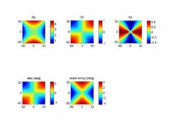
A specific example of this solution uses the example of a free-form surface (see Fig. 1). A contour plot of the surface sag, z-axis velocity and acceleration, as well as diamond-tool sweep angle and rake for a specific set of cutting parameters is prepared. The velocity and acceleration are plotted against the maximum allowed values, and when one or more parameters exceed their maximum magnitude (corresponding to a plot value below -1 or above +1), another set of parameters must be chosen to ensure that during the actual machining process, there will be no violations of physical limitations. As a result, the look-ahead buffer can be bypassed, as there is no risk of violating system limitations. The machining performance becomes highly predictable and ensures optimum surface finish for the given surface geometry.
Surface waviness
While form accuracy and surface roughness are always recognized as crucial for the optical performance of a lens or mirror, the surface waviness is often a somewhat neglected figure, probably because sufficient quality can be achieved by conventional machining methods such as polishing. Even by single-point diamond turning of rotationally symmetric surfaces, a low surface waviness can be accomplished by carefully choosing tools and machining parameters. Discretization of the optical surface only takes place along the radial direction of the part, and since the velocity along that direction is relatively modest, the discretization steps can be made quite small (in the range of 5 to 10 µm) and interpolation errors are negligible.
Again, free-form machining is a different story: discretization of the part takes place in both the radial and tangential directions, and in the tangential direction the discretization steps are generally between 0.1 and 1 mm defined by the surface geometry and block rate (the rate at which control points are fed to the controller). With such a sparse discretization, the high difference between two neighboring points can become large and the error resulting from the linear interpolation used between points can be significant. Furthermore, because of the way the part program is normally generated, the linear interpolation error is very coherent by nature and the end result--which occurred when one of our first mirrors was deployed in a HUD prototype--is that the image jumps around on the windscreen when the viewer's head moves in the eye box, as the image hits different facets of the free-form mirror.
The straightforward solution to this linear interpolation error would be to reduce the discretization steps in the tangential direction. However, the problem there is that the block rate cannot be increased conversely, and hence the machine increment per time would be significantly reduced and the machining time would become prohibitive.
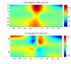
Another solution is to use a light post-polish by hand to smooth the linear interpolation error. Unfortunately, hand polishing can compromise the form accuracy and different kinds of waviness will result. Our alternative approach is to deploy a higher-order interpolation scheme by which the machine moves from point to point in the tangential direction in a highly nonlinear way true to the specific free-form nature of the surface being machined. A theoretical comparison of the discretization error by linear interpolation and by using nonlinear interpolation shows that the latter error can be reduced by four orders of magnitude (see Fig. 2). In the case of nonlinear interpolation, the theoretical error is well below the axis resolution of the system of 1 nm so that the waviness by interpolation is effectively removed.
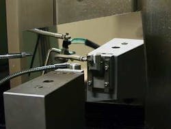
Kaleido has successfully developed and deployed tools for diamond machining of truly free-form mirrors up to 700 mm in diameter to effectively meet requirements for rapid prototyping of truly free-form optics accompanying the rollout of HUDs in the automotive industry (see Fig. 3). Form errors smaller than 3 µm peak-to-valley and mid-frequency waviness errors better than 70 µrad are routinely reached in rapid prototyping of HUD mirrors up to 400 x 300 mm in size with truly free-form surfaces as dictated by the requirement to project undistorted images of the windscreens of modern cars.
CHRISTIAN HOLME is cofounder and chief scientist and PALLE G. DINESEN is cofounder and chief sales officer at Kaleido Technology, Ryttermarken 15-21, DK-3520 Farum, Denmark; e-mail: [email protected]; www.kaleido-technology.com.


