JOEL BAGWELL
Engineers and scientists involved with optics and imaging are frequently faced with situations in which commercial off-the-shelf optics are to be integrated into a larger system. In some instances, the engineer or scientist encounters difficulties resulting from the optic moving unwanted light around in an unintended fashion. This so-called stray light is a common problem when piecing together optical systems. Fortunately, a variety of tools can be used to deal with stray light, one of which is blackening the edges of the optical elements. This option can be very straightforward for the optical engineer to implement, especially if edge-blackened optics can be obtained without resorting to custom fabrication.
A single-achromat example
While many custom optical systems use edge-blackened optics, very few commercial off-the-shelf optics are available with this stray-light-controlling feature. An example based on a single achromat demonstrates the benefit of using edge-blackened optics. It should be noted that the example examines the stray-light behavior of a single achromat in a specific, yet common lighting geometry. In practice, optical systems generally consist of more than one lens, and perhaps other types of optical elements as well. However, one can gain an appreciation of the possible benefits of edge-blackening the optics of a multielement system by examining the behavior of a single-lens system. It is generally safe to assume that as optical systems become more complex, the designer must be more vigilant in controlling stray light.
Consider a single achromat used to image a faraway scene, both with and without its edges blackened. When using lenses to look at objects far away, closer objects outside the field of view often send unwelcome light toward the lens. For example, if a lens is used to image a person who is a couple hundred yards away and a white wall is close to the user of the lens, stray light will emanate from the white wall, enter the optical system, and possibly cause stray-light problems.
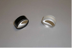
Using commercial stray-light-analysis software, optical designers can quantify stray-light effects on image quality. In this example, the differences between two versions of the same lens used to image the same scene are analyzed (see Fig. 1).
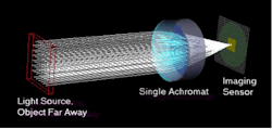
The single achromat is used to image a small faraway object (see Fig. 2). It should be noted that the only light arriving at the imaging sensor originates from the object of interest.To model the real-world stray-light situation, the software package allows the designer to apply different scattering properties to the edges of a lens. Using goniometric measurements from a scatterometer, a bidirectional scatter-distribution function (BSDF) was empirically derived for a ground-glass surface with the edge-blackening process applied. The BSDF data was than entered into the program to create a custom scattering model that accurately depicts the scatter properties of the blackened edge of a lens. Likewise, a diffuse, bare ground-glass scatter model can also be applied to the edge of the lens to represent the achromat without blackened edges.
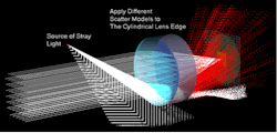
Now consider a situation similar to that in Fig. 2 with an additional light source fairly close to the lens, but outside the field of view (see Fig. 3). This new source could be a reflective wall, or even a friend wearing a white shirt who happens to be close to the user of the lens, but not within the lens's field of view. Fig. 3 qualitatively illustrates the effect of the non-blackened-edge scatter model applied to the edge of the lens under the aforementioned source geometry. The stray-light model changes the color of the light rays after scattering from white to red for ease of visualization.Even though the close-up object is outside the imaging system's field of view, light originating from the object scatters off the interior wall of the achromat toward the imaging sensor. In this example, the scattered light that arrives at the imaging sensor causes a loss in contrast of the primary image and is therefore undesirable.
Lowering the noise floor
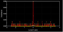
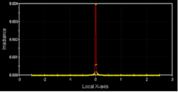
The optical designer can next analyze the stray-light characteristics of edge-blackened and non-edge-blackened cases by looking at their respective irradiance distributions of light at the imaging sensor. An irradiance-distribution plot corresponding to a single line profile or single row of pixels through the center of the image plane in Fig. 3 can be taken (see Fig. 4). Note the high level of the noise floor resulting from scatter from the ground-glass edge of the lens. In this instance, the stray light incident on the imaging sensor will cause a washout effect resulting in decreased image contrast.Of particular interest is the dramatic reduction of background noise due to the light-absorbing characteristics of the blackened edges. As a result, the user will observe greater image contrast and less sensitivity to surrounding objects outside the field of view, making edge-blackened optics a better imaging solution than traditional non-blackened optics.
In this example, the primary source of stray light is outside the imaging system's field of view. There is no shortage of literature on sources of stray light and it is not the intention of this article to create an all-inclusive list. However, other notable sources of stray light that produce similar effects to that described above may include excessively bright objects within the imaging system's field of view and specular reflections off of adjacent objects. In multielement systems, the problem above is compounded in that internal diffusely reflective surfaces (such as an unblackened ground-glass edge) may serve as yet another "source" of stray light. As an optical system becomes more complex, the possible stray-light problems increase quite rapidly, which greatly strengthens the case for implementing stray-light-controlling measures such as blackened edges.
Options for stray-light reduction
Stray light must be considered when implementing real-world optical systems. Unwanted light from sources outside the field of view of an imaging system must be anticipated and usually controlled if one is to successfully implement an imaging system. In some cases, stray-light conditions can cripple the optical system, while other systems are more tolerant of stray light.
The use of edge-blackened optics is one of a few methods at the designer's disposal to mitigate the technical difficulties presented by stray-light issues. Light baffles, light traps, and coarse dark interior surface finishing are also commonly used to control stray light. These methods, however, usually represent fairly significant changes or upfront considerations in the optical system design. On the other hand, implementing edge-blackened optics typically requires little to no change in existing mechanical designs, nor does it represent a significant cost increase, as is the case with some other stray-light remedies.
Recently, commercial off-the-shelf edge-blackened optics have become available, making their use much easier and less time-consuming. In the past, edge-blackened optics were "homemade" by scientists and engineers in the lab, as stray light problems were detected. However, the homemade edge-blackening process can become quite involved and time-consuming, with pitfalls such as possible nonuniform application of the ink, partial removal of the ink when cleaning the optic with solvents, and damage due to excessive handling. Conversely, the edge-blackening process for commercial off-the-shelf optics uses an automatic application of a specific RoHS (Restriction of Hazardous Substances)-compliant ink that is resistant to solvents. The result is a uniform, repeatable, rugged, and nonhazardous blackened edge with no time invested on the part of the user.
JOEL BAGWELL is an optical engineer at Edmund Optics, 101 East Gloucester Pike, Barrington, NJ 08007; e-mail: [email protected]; www.edmundoptics.com.
