FEMTOSECOND PULSE MANIPULATION: New tools compress and shape ultrafast pulses

Pulse manipulation methods, ranging from compact compressors to sophisticated pulse shaping are among the latest development in ultrafast laser technology. Congruent with the general trend toward simplifying femtosecond lasers, these tools are designed to be easy to operate and optimize. Several ultrafast-pulse manipulation methods commonly used, benefiting a variety of applications.
Removing GVD
The pulses at the output of most ultrafast lasers are not fully compressed to the transform limit because of uncorrected group velocity dispersion (GVD) accumulated inside the laser cavity. Such a dispersed pulse is called a "chirped" pulse. The GVD arises because the speed of light in glass, Ti:sapphire crystals or any other optical medium is a function of wavelength. The GVD is usually defined as the group delay dispersion per unit length, in units of s2/m. Group velocity dispersion also varies with wavelength, so for example, the group velocity dispersion of silica is +35 fs2/mm at 800 nm and −26 fs2/mm at 1500 nm. As a first approximation, the duration of an unchirped pulse after passing through an optical chain of known GVD, will be given by:where τin and τout are the unchirped (input) pulse and the chirped (output) pulse respectively, and DL is the total system GVD.
The final component in most ultrafast systems is often a pulse compressor whose purpose is to remove any GVD and produce transform-limited pulses at the sample or experiment. The compressor introduces a wavelength-dependent optical path delay--traditional compressors use a pair of dispersive bulk optics (prisms) or gratings for this. Most of these pulse compressors have been optimized for use with amplified laser systems where the pulses have been deliberately chirped (stretched) by several orders of magnitude to avoid damage to internal amplifier components.
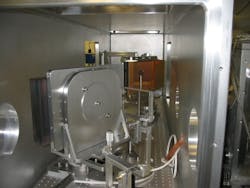
Oscillators don't need the huge correction capabilities required for amplified pulses and the unwieldy size that comes with these components, particularly compared to the small footprint of the latest one-box laser oscillators (see Fig. 1). Oscillator users often need pulse compression, however, especially when using newer hands-off products with the potential to produce very short pulses (shorter than 15 fs). Removing the GVD accumulated inside the laser cavity or through propagation in the external optical system is necessary in order to take full advantage of these short pulses. In turn, this requires a pulse compressor that offers fine control rather than massive correction, and ideally a small footprint as well. At Coherent, we designed our compact pulse compressor (CPC) specifically to meet these needs.
Instead of using prisms or bulky gratings, the CPC relies on chirped mirrors. The broadband dielectric mirrors for ultrafast lasers use many individual layers to deliver high reflection over a wide wavelength range. Each wavelength travels a different distance into the coating, and thus has a different pathlength or delay time. Chirped mirrors take advantage of this by introducing a negative GVD, as compared to transmissive components. The amount of negative GVD from a single reflection is small compared to the negative GVD of a pair of prisms or the positive GVD of a piece of glass, but is a perfect building block for correcting the GVD typical of today's laser oscillators.
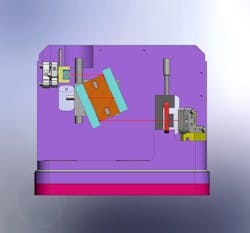
In the CPC, two chirped mirrors are pre-aligned parallel to each other in a rigid Super Invar assembly that maintains their angular alignment even as temperature changes (see Fig. 2). The laser beam enters at an angle and bounces multiple times before leaving the assembly. By tilting the assembly, the number of bounces can be increased or decreased. And by incorporating the assembly in a double-pass configuration, this rotation has no impact on the output beam direction.This arrangement provides "digital" control over GVD correction, with each extra double "bounce" raising the GVD correction in increments of 200 fs2. The maximum GVD correction is 2600 fs2. This control is still too coarse to optimize ultrashort pulses in the 10-to-20 fs range so the CPC also includes a sliding a glass wedge that's inserted into the beam path to continuously vary the GVD. As an example of its use, the CPC can take the output of a very broadband oscillator from an initial, chirped value of around 220 fs, to a compressed pulsewidth between 10 and 15 fs.
Who needs this short pulsewidth from a laser oscillator? A standout example is terhaertz generation and detection, where the transient optical wave creates a broadband terahertz pulse from a semiconductor antenna. A shorter pulse translates into higher peak power for the terahertz pulse as well as a broader frequency bandwidth for terahertz spectroscopy. Other applications include pump/probe spectroscopy where the benefit is enhanced temporal resolution.
Prechirping
Sometimes it's desirable to add negative GVD even to an unchirped a laser oscillator pulse to exactly counter the stretching effects of downstream optics. This is usually called "prechirping" and its main application is multiphoton excitation (MPE) microscopy. This application typically uses tunable one-box laser systems with pulse durations of longer than 100 fs. The problem is that the optics in the microscope can stretch this pulsewidth to hundreds of femtoseconds by the time it reaches the specimen, thus decreasing the peak power and the sample excitation--lower image brightness can result. The simplest solution is to design the laser oscillator to match the GVD characteristics of typical MPE microscopes. Very short pulses undergo substantial GVD stretching in the glass lenses. Conversely, longer laser pulses undergo minimal stretching and end with a shorter duration at the sample than initially shorter pulses. Pulsewidths from 130 to 150 fs produce the minimum pulse duration at the sample with a broad variety of microscope systems, of about 250 to 300 fs. However, some MPE applications would benefit from shorter pulses. In addition, next-generation microscopes may use multiple acousto-optic modulators (AOM) to offer fast random access, for applications such as live brain cell imaging. These microscopes will have much higher GVD, since just one AOM can introduce more than 20,000 fs2 of GVD.
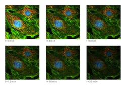
In response, MPE laser manufacturers now offer one-box ultrafast lasers with an integrated prechirping unit. The Coherent Chameleon Vision includes a module in which two glass prisms are used to produce negative GVD, which is adjusted by prism rotation. The GVD correction is fully automated and integrated with the main laser processor and can exactly offset the GVD from any microscope at every wavelength.Smooth continuous adjustment is important because even if the laser is always used with the same microscope and beam delivery optics, there is still the issue of wavelength tuning. Specifically, GVD in silica and glass varies strongly with wavelength. So a microscope that produces over 30,000 fs2 at the short wavelength limit of the laser (680 nm) might introduce closer to 10,000 fs2 at the laser's longest wavelength (over 1080 nm). Fortunately, the prism setup used for prechirping has a similar wavelength dependency: at 1080 nm the unit can correct from zero up to 15,000 fs2, and up to 47,000 fs2 of prechirp at 680 nm. Most important, this GVD adjustment has no effect on the output alignment of the laser, so the amount of prechirping can be altered during the imaging process. This supports excitation of multiple fluorophores each with optimum pulse width at the excitation wavelength, and also enables researchers to fully investigate the tradeoffs between laser power, pulsewidth, image contrast and sample photobleaching (see Fig. 3).
Pulse shaping: phase and amplitude
Dispersion correction has become more complex with shorter-pulse, wider-bandwidth oscillators. That's because real optics introduce higher order terms beyond the leading second order (fs2) term or GVD corrected by the pulse compression methods described so far. In terms of physics, the Fourier transform of a very short "perfect" pulse is a broad, smooth spectral profile with a shape similar to the central part of a Gaussian and with a flat phase profile. But ultrafast laser pulses rarely conform to this shape because of spectral biases in the optics or gain saturation effects at the peak of the spectral bandwidth. These amplitude distortions cannot be corrected by a pulse compressor. Even more subtle are phase distortions, where some spectral components have nonzero phase lag relative to other parts of the spectral profile. Again these can't be addressed by simple pulse compression.
When very short (less than 20 fs) pulses propagate through optical gratings or thick media, the corresponding higher-order phase and amplitude result in distortion of the final temporal profile. Fortunately, these effects can be eliminated by a relatively new type of pulse shaping device, allowing near-perfectly compressed pulses to be achieved, even starting from laser oscillators and nonoptimized amplified systems with considerable distortion. Moreover, this type of pulse shaper can also be used to exploit, increase and manipulate the effects of phase and amplitude differences, rather than eliminate them. Indeed, phase and amplitude shaping allows sophisticated temporal profiles to be created, including double pulses and "tailored" spectral profiles for selective excitation experiments.
An example of this type of pulse shaper is the Coherent Silhouette, which uses programmable phase and amplitude masks in conjunction with a zero dispersion stretcher. The stretcher laterally spreads the pulse as a function of wavelength and then recombines it without any chirping. In the middle of the stretcher, at the so-called Fourier plane, the beam is parallel (collimated) with a linear mapping of wavelength to lateral displacement.
A linear liquid crystal array—spatial light modulator (SLM)—is used as a programmable phase mask at this location. Increasing the voltage at any of the SLM pixels retards the phase of light passing through that pixel. For an array with 128 pixels, the spectral bandwidth of the laser pulse is divided into 128 equal segments and the phase of each of these wavelength segments can be arbitrarily changed by adjusting the voltage to that pixel. By including an optional polarizer and second SLM, this approach allows the pulse amplitude (intensity) to also be adjusted as a function of wavelength.
The second part of this closed-loop system is a compact multiphoton intrapulse interference phase scan (MIIPS), which senses phase by frequency-doubling the beam and observing interference between different parts of the doubled and un-doubled beam (see www.laserfocusworld.com/articles/292409). In operation, the system controller works by rapidly and automatically imposing a phase delay profile using the system SLM and observing the result with the MIIPS unit. This enables it to characterize the phase and amplitude characteristics of the beam. The controller then iteratively adjusts the SLM to create the desired phase profile across the laser's spectral bandwidth. The uncorrected and corrected phase information can also be directly accessed by the operator.
A key aspect of this two-part system is that the desired phase/amplitude profile can be created anywhere in the beam path, wherever the compact fiber-coupled MIIPS head samples the beam, via a low-loss beamsplitter (see Fig. 4). The pulse-shaping unit is usually placed at the output of the oscillator. The desired pulse shape can be synthesized at this location or after downstream optics, simply by relocating the MIIPS sensor head. Where the beam then passes through one or more ultrafast amplifiers, the MIIPS head can be placed at the output or at the interaction zone in an experiment.The most simple and widely used pulse-shaping application is to produce transform-limited pulses from amplified systems. In a regenerative amplifier, the ultrafast pulse passes through the Ti:sapphire gain medium tens or hundreds of times, gaining intensity with each pass. Because the gain has a wavelength dependence, with a peak near 800 nm, the center of the bandwidth is amplified more than the wings, creating a narrower spectral profile for the amplified output pulse in a process called gain-narrowing. However, a pulse shaper can tailor the amplitude spectral profile of the oscillator pulse before it enters the amplifier to automatically offset all gain distortions and other spectral irregularities in the amplifier and oscillator. This facilitates the production of transform-limited pulses, even from a system not optimally aligned or optimized.
Another sophisticated application is in quantum reaction control. Decades ago, the advent of laser photochemistry appeared to offer the promise of reaction control, where a laser could be used to select a specific unimolecular reaction outcome, even where other outcome(s) might be kinetically and/or thermodynamically preferred with broadband light. This promise was mostly unfulfilled because of fast nonradiative transitions (scrambling of the absorbed energy). However, more recently, some researchers have discovered that by modifying the amplitude and phase profiles of ultrafast pulses, the branching ratio of photochemical reactions can be influenced. This discovery generated a whole new series of experiments called quantum reaction control.
Marco Arrigoni
Marco Arrigoni is vice president of marketing at Light Conversion (Vilnius, Lithuania). He previously served as director of marketing at Coherent (Santa Clara, CA) from 2007 through 2023.
David Armstrong | Product Manager, Coherent
David Armstrong is a Product Manager at Coherent (Santa Clara, CA).
Nigel Gallaher | Product Manager, Coherent
Nigel Gallaher is a Product Manager at Coherent (Santa Clara, CA).


