OPTICAL TEST EQUIPMENT: Measuring aspheres with scanning and imaging technologies
ILKA MAHNS
Aspheric lenses can improve the performance of complex optical systems; in addition, because fewer optical elements are required in many cases, they can also decrease costs. One of the main challenges to manufacturing highly accurate state-of-the-art aspheric optics and molding tools is in making reliable and precise measurements of the manufactured surfaces.
Different asphere-fabrication processes require different measurement methods. In ultraprecise processes, aspheres are fabricated by diamond turning or polishing. In contrast, aspheres for cell-phone cameras are mass-produced by molding. Lens manufacturers must carefully choose the appropriate optical test instrument for their production process.
Centration-error measurement for aspheric lenses in optical production is also important. The centration error of a lens influences its optical properties and it is essential that lens manufacturing machines produce lenses without a tilt.
Aspheric surfaces can be tested using either scanning or imaging techniques. Scanning systems can be classified as either tactile or noncontact; imaging technologies include Shack-Hartmann wavefront analysis and Twyman-Green interferometry with the use of a computer-generated hologram (CGH). All these methods provide surface topography, but differ in resolution, sample diameter, measurement time, and so on.
Scanning technologies
A tactile scanning system relies on a probe tip such as a ruby ball or diamond. The tip is scanned over the surface of the asphere, contacting the surface of the lens during the entire measurement process. Variations in topography produce tip movements that are detected and analyzed to obtain the topography of the asphere.A scan can be performed linearly across the zenith of an asphere, or as a circular scan by rotation of the asphere around its optical axis on an air bearing. Tactile scanning provides results with accuracies ranging between 0.05 to 0.3 µm depending on the inclination angle of the asphere; however, scanning a single lens takes several minutes. Furthermore, tactile systems are very prone to producing scratches and other damage while moving the tip over the asphere. To prevent any scratches, the surface of the asphere under test must be perfectly clean. One example of a standard tactile scanning system is the Panasonic UA3P series, which is a coordinate-measuring machine (see Table 1).1
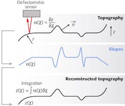
TABLE 1. Specifications and comparison of the deflectometric with AspheroMaster and the tactile method Panasonic UA3P-3001In the noncontact deflectometry technique, the slopes at all points on the aspheric surface are detected with an optical sensor. The sensor includes a fiber-coupled laser diode and several optical elements that focus the laser beam on the surface of the asphere.
In a standalone test machine called the AspheroMaster, for example, the optical sensor is guided without physical contact around the sample while the asphere rotates around its axis on an air bearing. The 3D topography then is calculated with the help of mathematical algorithms that integrate the slope angles (see Fig. 1).2, 3 In this way, the deviation between the measured asphere and the theoretical form is determined.
The small spot size (25 µm) of the deflectometric sensor ensures detailed information about the surface with high slope resolution (up to 35 µrad). The measurement depends only on the reflection of the laser beam, so surface damage does not occur.
Furthermore, a compact deflectometric sensor can be integrated into a manufacturing machine for surface-form measurements during the production process.4 An upgrade of such a deflectometric sensor in a manufacturing machine has been a part of the German Federal Ministry of Education and Research project “MicroAdapt—Adaptive Manufacturing of Optical Components with a Machine Integrated Form Test.”
Imaging technologies
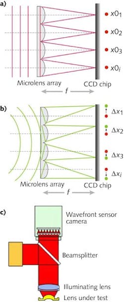
In the Shack-Hartmann noncontact imaging technique, the wavefront produced by the asphere is sensed by a CCD camera placed at the focal plane of a microlens array.5 The incoming wavefront is sampled by the lenses of the microlens array; the resulting spot pattern on the camera would, in the case of a perfect plane wavefront, be evenly spaced (see Fig. 2). Any aberration introduced by the sample leads to a curvature of the wavefront; any local wavefront tilt induces a measurable shift of the corresponding focal-spot position.For the topographical measurement of an aspheric surface a setup in reflection is required. One example is the WaveMaster Reflex, which includes a wavefront sensor, a beamsplitter, and an illuminating lens (see Fig. 2c). This system can be used to test single lenses or for batch testing of wafers (made of glass, each wafer contains many small glass aspheres) and other components in mass production. In contrast to the scanning methods, the whole sample is measured in one step that takes less than 5 s per lens (see Table 2). Measurements are accurate to better than λ/10 peak-to-valley and provide lateral resolved information about deviations from the ideal lens shape.
TABLE 2. Specifications and comparison of the Shack-Hartmann wavefront sensor WaveSensor and interferometry with CGHs µPhase7
Another noncontact imaging system, the Twyman-Green interferometer, is based on a monochromatic laser light source. The surface quality of the asphere is determined from the fringe pattern; for an aspheric surface that deviates from a sphere by a large amount, a null optic such as a CGH can be used to compensate for the interferometer’s insufficient dynamic range.6 The CGHs have to be made individually for each type of measured lens, increasing setup time and cost.
Centration-error measurement
In addition to testing the surface form of an asphere, the lens manufacturer must ensure that the lens surface is free of tilt or centration errors, as these errors influence the optical properties of the lens.An example instrument for centration-error measurement of aspheric lenses is the OptiCentric system equipped with a chromatic confocal sensor, the AspheroCheck sensor. The instrument contains an electronic autocollimator with a CCD camera and an ultraprecise air bearing that serves as a reference axis during the measurement of the lens rotating on the bearing.
The centration error of a lens with one aspheric and one spherical surface is determined by measuring the deviation of the paraxial center of curvature with respect to the reference axis, and the tilt of the aspheric symmetry axis with respect to the reference axis. Lenses with diameters from 0.5 to 600 mm can be measured.
Today, centration-error measurement is a standard quality-control procedure in the manufacture of DVD and Blu-Ray optics. Depending on the lens, an accuracy in the arcsecond range can be reached.
REFERENCES
1. http://www.panasonicfa.com/
2. W.D. van Amstel et al., Proc. SPIE, 3782, 320–327 (1999)
3. A.R. Davis et al., SID Int. Symp. Digest Tech. Papers, 32, 1, 934–937 (2001).
4. S. Krey et al., Proc. SPIE, 77180, 77180C-1 (2010).
5. R.V. Shack and B.C. Platt, J. OSA, 61, 656 (1971).
6. S. Reichelt et al., Proc. SPIE, 4778, 158–168 (2002).
7. T. Blümel and R. Kafka, HLEM Meeting (2010).
ACKNOWLEDGMENT
AspheroMaster, WaveMaster, OptiCentric, AspheroCheck, and µPhase are registered trademarks of TriopticsGmbH.
Ilka Mahns is a physicist in the R&D Department at Trioptics, Hafenstrasse 35-39, 22880 Wedel, Germany; e-mail: [email protected]; www.trioptics.com.

