Rotary sensor for industry uses polarization of light for sensing
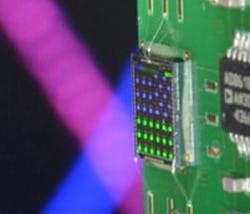
| A polarization sensor mounted on a test board measures the angle of polarization rotation. (Copyright Fraunhofer IIS) |
Researchers at Fraunhofer Institute for Integrated Circuits (IIS; Erlangen, Germany) have developed a new kind of rotary sensor that combines precision measurement with flexible handling, allowing it to be customized to specific measurement tasks. The scientists will be presenting their prototype at the Sensor + Test trade show in Nürnberg, Germany from June 3 to 5, 2014 (Hall 12, Booth 12-537).
There are currently two types of rotation-angle sensors on the market, based on either magnetic or optical measuring principles. Magnetic sensors are durable and dirt resistant, giving them an advantage in harsh environments. They are, however not as precise as optical sensors (rotary encoders). These in turn are not very flexible to use, since they must be precisely mounted in a fixed position on the object being measured.
The Fraunhofer IIS device relies on light polarization; a polarizing film is attached to the test object (a drive shaft, for example) and light directed at it. A readout module is mounted in the beam of light; several wire-grid microstructures are arranged in a matrix on the sensor chip (these grids can be manufactured using standard CMOS techniques). The angular position of the shaft is calculated when the polarized light strikes the lattices.
"To obtain a definite measurement of the angular position of a shaft, we need at least three grids that are each structured in different directions," says Norbert Weber, group manager at the IIS. "Depending on the measuring task, we can also add further grids, thus adapting the chip to suit the specific requirements of customers while increasing measurement accuracy."
The design is not as precise as conventional optical sensors, but the Fraunhofer IIS sensor is significantly more robust and can be relatively flexibly positioned. "The chip does not even have to sit directly on the optical axis -- the only thing that matters is that it is located within the light beam," says Weber. Another advantage is that even if the shaft wobbles slightly, the results are not affected as long as the beam is wide enough.
Source: http://www.fraunhofer.de/en/press/research-news/2014/may/right-spin.html
