Deformable mirrors correct wavefront errors
Precision actuators improve imaging capabilities of ground-based monitoring systems and telescopes by distorting deformable mirrors to compensate for atmospheric turbulence.
Mark A. Ealey
Adaptive optics have become indispensable elements of high-performance optical systems that image through the atmosphere, compensating for image degradation caused by atmospheric turbulence. A typical system includes a wavefront sensor, a deformable mirror consisting of a reflective membrane backed by precision actuators, and support hardware and software. The sensor detects errors in the incoming wavefront; the computer quantifies these errors and commands the actuators to distort the deformable mirror to induce an equal and opposite wavefront error in near real time. Given a sufficiently responsive deformable mirror, an adaptive optics system can significantly improve system imaging performance.
Unique as an optical component, the deformable mirror must have a quality optical surface that can be contoured and controlled to a fraction of a wavelength of light. The key element is the actuator, which must provide precision motion for nanometer-scale wavefront control while providing a stable structure for a high-quality optical figure. It must be thermally and temporally stable; being in a dynamic environment, it must also withstand high tensile loads and high cycle fatigue.
First proposed during the 1950s, deformable mirrors did not reach technical maturity until the late 1980s, and manufacture did not become routine until the mid-1990s. The major technical issue was the actuator. During the 1970s, lead zirconium titanate (PZT) actuators in both epoxy-bonded and cofired forms were used in deformable mirrors but were unable to provide the right blend of accuracy and dimensional stability. Mirrors made with PZTs degraded in optical quality over time, and hysteresis, creep, and capacitive heating effects placed undue requirements on the servo control system.
After a decade of development during the 1980s, deformable mirrors incorporating cofired actuators formed of electrostrictive lead magnesium niobate (PMN) finally delivered the promised ability to control the optical surface to a fraction of a wavelength of light. Because the actuators were electrostrictive, they did not exhibit the aging and creep phenomena associated with PZT devices; for the first time, deformable mirrors were available with an optical quality comparable to those of other optics in a telescope. Routine fabrication of PMN actuators and their mirrors did not happen until the mid-1990s; the number of actuators ranged from 37 to 349 channels (see Fig. 1).
High-power amplifier technology also matured during this time; devices were built that could handle both the high voltage and current demands of deformable mirrors and could be integrated onto printed-circuit boards.
Deformable-mirror configuration
Two design approaches have been developed for deformable mirrors. In one configuration, the mirror structure includes a mechanism housing the actuators that permits engineers to replace faulty actuators. This design tends to suffer from mechanical hysteresis, poor optical figure quality, and cyclic fatigue. The mechanism needed to enable replacement is subject to failure as often as the actuators themselves, and achieving optical tolerances with actuator placement is also difficult.
The other approach is to make the design as structurally simple as possible. The actuators are bonded between a thin glass facesheet and a thick glass base. Stress loads and induced-strain levels are optimized during design to allow an infinite number of cycles. The actuator assembly, being the structural element, must be reliable during both manufacturing and operational environments.
Displaying less than 1% hysteresis, PMN does not impact the servo control system. It does not age or creep, critical factors in attaining dimensional stability at optical tolerances. With a tensile strength in excess of 2800 psi, it can withstand the cyclic environment and push-pull operating requirements of a de formable mirror, and it is voltage controlled.
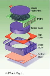
A total of 5000 actuators have been used in the manufacture of 16 deformable mirrors during 1996. A typical commercially available deformable mirror consists of a glass facesheet, PMN actuators, a glass base structure, and a metal bezel (see Fig. 2). Printed-circuit cards aid in the assembly of actuators by allowing the installation of individual rows of actuators. A large optical base provides a reaction mass against which the actuators push, which ensures that all the displacement force goes into the facesheet rather than the backing structure.
Performance issues
Actuators are directly responsible for the performance of a deformable mirror. Production of actuators that can withstand the stress of high cycle operation and can withstand environmental effects such as humidity, shock, and temperature is key to insuring mirror performance. Structural tradeoffs determine actuator deflection, force, and stiffness requirements; actuator form, fit, and function directly affect mechanical, optical, and electrical performance.
The devices are fabricated using a cofiring process, with a structure consisting of multiple thin layers (125 to 250 µm) that are diffusion bonded at the time the electrostrictive material is sintered to its final density. Net positive displacement is a superposition of the strain from the individual layers. The actuators feature tensile strengths in excess of 3500 psi and strain levels of 1000 ppm, while operating on less than 100 V. Thermal expansion of PMN is below 1 ppm/°C, while the elastic modulus is greater than 16 ¥ 106 psi, and the transfer function is highly linear.
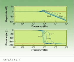
From an electrical standpoint, electroceramic actuators are simply capacitors with additional electromechanical properties. Actuator capacitance determines amplifier current requirements and inherent bandwidth limitations by establishing a bandwidth or cutoff frequency above which the amplifier applies reduced voltage; bandwidth thus increases for lower operating voltage and actuator capacitance (see Fig. 3). For a given stroke, the voltage necessary to provide a certain field can be reduced by making the actuators as thin as possible. However, the increased number of layers as well as the reduced thickness of each layer will cause capacitance to increase quadratically.
Role of influence function
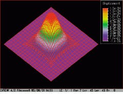
The correction capability of a deformable mirror is ex pressed by the mirror influence function, which is in turn defined by the shape of the mirror surface when pushed by an actuator (see Fig. 4). Simple beam theory shows that a continuous-facesheet deformable mirror automatically constrains the influence function to certain shapes, controlled by factors such as facesheet stiffness, actuator stiffness, and actuator pad geometry. More than any other factor, facesheet stiffness determines how well the mirror will simulate the phase measured by the wavefront sensor.
The surface of the deformable mirror must be contoured to that of an optical wavefront and controlled to a fraction of a wavelength of light. First and foremost, the component has to function as a quality optic. The stiff actuators present a hard surface for the polishing lap; regions directly over the actuators experience high wear, while unsupported areas between actuators tend to sag away under pressure, reducing the material removal rate in those locations. If the mirror facesheet is too thin, a quilted mirror surface results. Thickening the facesheet increases its stiffness between actuators, reducing the polishing ripple and improving the optical figure.
Thermal stability of the mirrors is also critical. In tests of the adaptive optical system at the 10-m telescope of the W. M. Keck Observatory (Mauna Kea, HI), scientists observed little measurable change in surface figure of the deformable mirror over a temperature range from 20°C down to 0°C (see Fig. 5). Key to this stability is the electrostrictive response of the PMN actuators. Because it is not a poled electroceramic, PMN also does not degrade over time, ensuring a stable optical figure for many years of operation. o
FIGURE 2. Typical deformable mirror consists of a glass facesheet as the front reflector, PMN actuators to deform the optical surface, a glass base structure to provide a thrust base for the actuators, and a metal bezel.
FIGURE 3. Bode plot for a single high-voltage linear amplifier channel with actuator loads ranging from 1 to 25 µF shows the inverse relationship between bandwidth and actuator capacitance.
FIGURE 4. Influence function measured on Xinetics deformable mirror show 8% at the nearest neighbor, which agrees with both parametric and finite-element analyses.


