Optical fabrication relies on tried and true methods
Optical fabrication relies on tried and true methods
New developments in optical fabrication build on traditional techniques to achieve volume production and part-to-part consistency through reduced cycle times and automation.
Optical production houses routinely manufacture optics to tight tolerances, but the basic techniques for achieving this accuracy have changed little in hundreds of years. In the optical-fabrication process, the part is first roughly shaped, or generated, from an optical flat. This surface is ground into a smooth surface to remove subsurface damage from generation and to bring the shape, or figure, close to prescription (see "The language of optics," p. S8). Finally, the ground surface is polished to an optical quality surface.
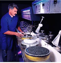
To generate flat optics, fabrication houses typically work the materials with diamond-impregnated tools, while for spherical surfaces, the mounted part is rotated while pressed against a hollow, cylindrical cutting tool that also rotates. The grind process relies on a simple mechanical phenomenon. If two roughly flat surfaces are brought into contact and rubbed together, they will wear down the high spots on one another and become increasingly flat (see photo). Similarly, roughly spherical surfaces of equal convex and concave radii brought into abrasive contact will become increasingly spherical. Polishing involves this mechanical process but may also incorporate chemical reactions to achieve a smooth optical surface.
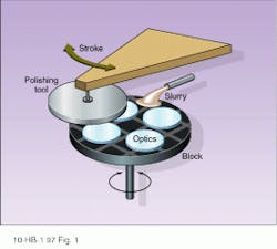
During grind and polish, parts are mounted, or blocked, on a tool that is either flat or spherical, then brought into contact with an appropriatedly shaped tool (see Fig. 1). The radius of curvature of the part limits the number of parts of a given diameter that can be fabricated simultaneously, which makes highly curved parts more expensive to produce in volume.
Parts are typically fixed to the block with pitch, an extremely viscous, tar-like substance. In the case of finely toleranced parts, unevenness in the surface of the pitch can induce gross tilt or local variations in the part surface, introducing errors during the fabrication process. To produce flat parts with extremely good surface parallelism, manufacturers avoid adhesives and instead apply the blanks to a contact plate for the grind and polish phases (see Fig. 2).
Grinding tools are generally cast iron that is cut with circular grooves. A slurry consisting of water and an abrasive enhances removal at the interface between tool and part. During polishing, the tool is covered with pitch, which cold flows under pressure to conform to the shape of the workpiece. The particles of the polishing compound embed themselves in the pitch to produce a smoothing effect. Grinding and polishing must be performed in separate production environments to prevent large airborne grind particulates from contaminating the polishing slurry--particles in grinding compounds typically range from 5 to 30 µm in diameter, while polishing compounds are milled to 0.5 to 5 µm.
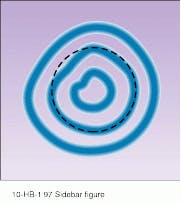
A fundamental tenet of optical fabrication holds that one can manufacture a part only to the degree that one can measure it, making precise, accurate, and repeatable metrology critical to the production of high-quality components. During the production process, opticians test surface figure and finish with master test plates or optical flats, studying fringe patterns to locate figure errors (see Fig. 3). For quality control of finished components, the use of laser-based interferometers has become common practice. These instruments use coherent optical interference to ma¥the surfaces of components, making extremely precise, quantitative measurements.
Trade-offs and challenges
Several parameters of the fabrication process can be varied to adjust tolerances or correct errors that appear during production. To improve surface figure, for example, opticians adjust the stroke length and stroke rate of the tool, changing the length of time the tool will dwell and remove material from a given region of the workpiece. To increase the material-removal rate, opticians can raise the spindle speed or vertical pressure applied to the tool. These measures can reduce production time and, hence, component cost, but they also limit control over the optical figure of the components.
A variety of grinding abrasives, polishing compounds, and polishing la¥materials are available for fabrication. Manufacturers can thus optimize the process for materials of varying hardness, such as crystalline materials. The chemical and mechanical aspects of polishing can also be tailored to achieve de manding surface-roughness values.
Certain specifications are difficult to maintain simultaneously during the polishing process. For example, it is challenging to hold tight tolerances on both flatness/irregularity and surface quality. The component generally reaches the desired optical figure before attaining the required surface finish. Further polishing designed to achieve extremely low surface roughness may actually degrade the surface figure. For some high-energy applications, however, this trade-off is acceptable.
Holding a surface flatness/irregularity specification of better than l/10 is challenging on parts for which the diameter-to-thickness ratio is less than 6:1. When such thin parts are deblocked after polishing, they tend to "spring" back to their un stressed shape and lose their figure. The use of a continuous polisher in which the parts remain unblocked during fabrication allows manufacturers to avoid figure changes from springing.
Modern developments
Although the basics of optical polishing have not changed, technology has advanced to meet current economic and performance requirements, for example, through computer-controlled grind and polish technology. Programs drive specially designed machines to perform a series of shaping and finishing operations. Technicians load lens blanks into the machine, which automatically brings each optic from rough to finished form. To facilitate automated parts-handling, the workpieces are mounted on a vacuum chuck rather than blocked in pitch. Given the right combination of run quantity, tolerance, radius of curvature, and part diameter, computer-controlled fabrication can can offer a cost and time advantage over traditional polishing,
Some optics applications require very low surface roughness. For example, the finesse of high-performance etalons is usually limited by surface and coating defects. Standard optical polishing yields typical surface-roughness values of 5 Å rms. To produce components capable of achieving a finesse of greater than 10,000, surface roughness must be lower than 2 Å rms. To meet this challenge, Newport Corp. (Irvine, CA) developed a superpolishing process.
Newport has also developed a technique for the fast, economical production of precision optics. This hybrid method uses a proprietary combination of high-speed and high-precision polishing techniques to minimize the time, and, hence, cost required to achieve a given figure. The high-speed portion of the process incorporates a polyurethane la¥rather than a pitch lap, because pitch is too soft for the speed and pressure combination involved. With the accelerated approach, Newport has reduced the production time for optical flats with surface finishes of l/10 and surface qualities of 10-5 from 16 hours to three hours.
Although computer-controlled techniques have their place, most commercial optical-fabrication houses still rely on well-established, time-honored techniques. The reason for this is simple--it is the best way known to achieve good results. Most of the new developments in the field are not aimed at increasing product performance, but at improving the economics of volume production and part-to-part consistency through shorter cycle times and automation. o
Numerous small, flat parts can be processed simultaneously using traditional polishing techniques.
Number of fringes in an optical test indicates the difference between the radius of the test plate and test piece (power). The deviation of fringe shape from perfectly circular shows the amount of irregularity in the piece.
FIGURE 1. During the polishing process, optics are placed on a block. The bottom tool can rotate only about the vertical axis. The to¥tool uses a ball-in-socket mount for complete freedom of angular motion. In operation, the bottom tool rotates and the to¥tool moves back and forth in an arc, a movement called the stroke; friction causes the to¥tool to rotate as well.
FIGURE 2. A continuous polisher can produce very-high-flatness parts at high volumes. Parts are not affixed to a block, so they can be removed or added as needed.
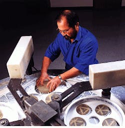
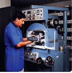
FIGURE 3. Optician checks the radius of curvature of a part with a spherometer; the workpiece shown has just been generated, or machined, to the rough optical prescription.
