Optical-layer monitoring safeguards fiberoptic networks
by Ulf Olin And Simon Sandgren
The acousto-optic properties of chirped fiber Bragg gratings enable both fast channel monitoring and detailed performance monitoring using the same equipment.
The increasing use of the Internet, with the transmission of text, still image, and movie data, increases the demand for bandwidth in transmission networks. Global fiber-optic communication networks handle the majority of this traffic, but capacity still needs to increase. And to access more of the potential bandwidth of optical fibers, the bandwidth of each channel must be increased, the channel separation must be reduced, or both.
In addition, network flexibility must increase by transforming point-to-point and ring structures into mesh-like and easily reconfigurable topologies that will fit the changing demands of customers. Thus, functionality from tunable optical add/drop multiplexers, tunable lasers, dynamic gain equalizers, and so on, will be added to the network. That said, this added functionality and capacity make it crucial to also provide fast and accurate spectral information from all channels in the network.
In terms of operator revenue, it is also important to minimize the operations cost per bit, while still maintaining the required quality of service. Thus it is essential to have instrumentation distributed in the network that warns when the network is not operating according to specifications and provides input for protection switching, equalization, and span monitoring.
With a well-monitored network, the service provider can take appropriate actions before transmission errors occur, which is important when dealing with gradually degrading devices like lasers and amplifiers. This helps to maximize network uptime and to avoid service-level agreement violations.
A new and fast spectral-scan mechanism, based on the acousto-optic properties of chirped fiber Bragg gratings, provides the means for combining both fast optical-channel monitoring and very detailed optical-performance monitoring in the same optical-layer monitoring equipment. This means that the same instrument can be used in both fast-feedback control loops for dynamic-gain-equalizer modules, as well as for performing detailed monitoring and logging of channel data such as wavelength drift and optical signal-to-noise ratio. Thus, operators now can use a uniform monitoring system for the network, resulting in decreased space requirements and lowered training and maintenance costs.
Optical layer monitoring
Optical layer monitoring (OLM) deals with the accurate measurement, performed within milliseconds, of the physical properties of the light being transmitted, such as optical power, wavelength, and optical signal-to-noise ratio (OSNR). The monitoring equipment is distributed throughout the network to detect, identify, and localize faults and deviations from specifications in the network. Because the measurement of the DWDM spectrum is performed within milliseconds, it is also possible to use the OLM equipment to generate alarms for protection switching.
The OLM equipment provides high resolution, fast detection capabilities, and high signal processing power to ensure accurate monitoring with the densest channel spacing and highest channel counts. In addition, adaptation to the various types of equipment found in a modern optical network, also requires flexible and highly customizable communication interfaces. Thus, by combining the measurement performance and the versatile communication interface, this instrumentation offers the channel control that is the catalyst for intelligent optical networks.
Modes of operation
With optical networks transforming from a point-to-point topology toward a meshed topology, the traditional methods for performance monitoring are becoming less effective. The number of optical amplifiers (EDFAs) is increasing and the optical-electrical-optical (OEO) conversion nodes (where bit-error-rates (BER) can be measured) are being pushed to the edges of the network. Additionally, the increased number of optical crossconnects (OXCs) and optical add/drop multiplexers (OADMs) are adding complexity to the network. Monitoring network performance in the optical domain can help service providers trace problem trends beyond data layer fault parameters (such as BER).
Optical performance monitoring (OPM), provides advanced spectral analysis, in which the center wavelength, optical power, and OSNR are determined for all DWDM channels in a time frame of 0.1 to 1 s. Optical channel monitoring (OCM) involves a fast analysis of the optical power for all channels. As this monitoring can be performed in a time frame of 10 ms, it can also be used for protection switching in an optical network. For complete optical layer monitoring, the functionalities from OPM and OCM should be simultaneously available in one unit.
Spectrometer design
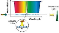
A spectrometer is at the heart of an optical-layer monitoring system. Typically 1% to 10% of the light in the transmission fiber is tapped and launched into the spectrometer module. The spectrometer is either implemented with a scanning optical filter or with a dispersive element, like a grating, that distributes the optical spectrum onto a photodetector array. Scanning devices traditionally consist of Fabry-Perot filters with tunable mirrors. This serial processing of the spectral information is normally slow (approximately a second for a complete spectrum). The other approach, with the photodetector array, performs the processing in parallel. Thus, the acquisition time becomes shorter. However, a faster way of making a scanning filter is to let a short acoustic pulse traverse a chirped fiber Bragg grating (see Fig. 1 and 2).
FIGURE 1. Scanning filter building blocks include broadband reflector, acoustic actuator and a chirped fiber Bragg grating. The light passes through a circulator to a broadband FBG reflector tuned to either the L- or C-band. This construction eliminates any scattered light outside the specified wavelength band. The filtered light returns to the circulator where it is directed to the scanning filter, made by the chirped FBG and the acoustic actuator. A low noise photo-detector device measures the power in the filtered optical signal.
The acoustic actuator generates a short acoustic pulse of a well-known shape and amplitude in the fiber. The pulse opens up a local transmission window, with high side-mode suppression, that shifts in wavelength as the pulse traverses the grating. The detector is continuously tracking the amount of light passing through the fiber and the optical detector response vs. time, thus, corresponds to the optical spectrum. As the sound velocity in the fiber determines the filter tuning speed, the scan time for the whole C-band can be less than 0.1 ms, which makes this scanning technology even faster than the parallel photodetector array-based approach.
A fast detector and an analog-to-digital converter are continuously monitoring the amplitude of the optical signal transmitted through the scanning filter. The optical signal is converted to the electrical domain, amplified and stored in data memory for further data processing. For OCM measurements, the signal processing electronics checks the status and reports anomalies of every monitored channel. For OPM measurements, the spectrum data is stored and averaged for a number of cycles. When the averaging process is complete, the calculation of the center wavelength, optical power and OSNR for all channels is performed.
Alarms
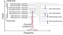
With the OLM equipment, all channels are monitored on a real-time basis. If a predefined parameter limit is exceeded, alarms will be generated. Each parameter is monitored by using two types of fault states: Warning and Alarm (see Fig. 3). Warning is a less critical fault level, indicating that something might be degrading though the system is currently in normal operation. An alarm indicates that one or more of the channel parameters has exceeded its set limits. To avoid generating an alarm for noise sections in the optical input signal, each threshold level is given a certain amount of hysteresis. This principle of hysteresis involves split levels for rising and falling signal values. The monitoring parameters can be individually configured for each channel.
Networking example
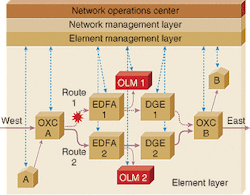
In the example of sender A transmitting information to receiver B, initially, the network is configured to use the upper route for the traffic between A and B (denoted as 1; see Fig. 4). A channel failure appearing in Route 1 is detected by the OCM functionality of the optical-layer monitoring equipment OLM 1. Then, OLM 1 sends an alarm to the management layers that reconfigure the network so that traffic between A and B take the lower route (denoted as 2). As the traffic load in the lower route has now changed, OLM 2 sends control information, via the element management layer, to the dynamic gain equalizer (DGE 2) to balance the different channel powers. To avoid data loss, this network reconfiguration should not take more than 50 ms from the failure time.
Another network example concerns provisioning. If A wants more capacity to B he can ask the operator to provide more channels for him. In this case, the network operations center reconfigures the two OXCs such that new channels are available between A and B. Again, when new traffic is added to the network, it is important that the OLM equipment can ensure that the traffic is spectrally balanced and that the optical powers and the OSNR are sufficient for the information to reach the respective receiver points.
As this example points out, the OCM and the OPM functionalities are often requested at the same points in the network. Thus, the OLM equipment with combined OCM and OPM functionalities is more cost-efficient for the network.
ULF OLIN is manager for optics R&D and SIMON SANDGREN is a product manager at Proximion Fiber Optics AB, Skalholtsgatan 10B, SE-164 40 Kista, Sweden; e-mail: [email protected].


