Wavefront correction extends the capabilities of large-aperture Nd:YLF laser rods
Magnetorheological finishing yields diffraction-limited performance from laser materials using proven technology developed for the optics fabrication industry.
High-energy, high-average-power lasers with diffraction-limited performance find important applications in pumping nonlinear optical processes, such as the optical parametric chirped-pulse amplification (OPCPA) system that will serve as the front end of the Omega (extended performance [EP] petawatt laser currently under construction at the University of Rochester’s Laboratory for Laser Energetics (LLE). Optical parametric chirped-pulse amplification is a variation of the chirped-pulse amplification (CPA) technique pioneered at LLE.1, 2 In OPCPA, a stretched ultrafast seed pulse is amplified using optical parametric amplification (OPA), which can provide gain over an extremely broad band.3, 4 In OPA, energy is transferred from a short-wavelength (2 ω) pump beam to longer-wavelength amplified signal (1 ω) and idler beams.
Pump-laser beam quality is crucial
Successful operation of an OPCPA system depends critically on the performance of the pump laser because many characteristics of the pump laser are transferred to the amplified signal beam, including the spatial- and temporal-intensity profiles. The pump-laser wavefront quality is of particular importance because excessive wavefront gradients will cause phase mismatching of the OPCPA process reducing efficiency and degrading the beam quality of the amplified signal.
The OPCPA pump laser for Omega EP must deliver approximately 2-J pulses at 1 ω with a 5-Hz repetition rate to achieve the greater than 250-mJ OPCPA output-pulse energy. This energy and repetition rate are required to provide enough signal to align the Omega EP grating pulse compressor at the end of this large, multipass CPA laser system. Due to its relatively weak thermal lensing, linearly polarized gain, and strong natural birefringence, Nd:YLF is a good choice for power amplification. The high-saturation fluence for the laser gain in Nd:YLF at 1053 nm also minimizes the effect of gain saturation on the pump pulse’s temporal shape, which is important for highly efficient OPCPA.5 A large-aperture laser rod is required to extract the required energy without deeply distorting the temporal pulse shape.
In the OPCPA pump-laser system, single-frequency pulses from a single-longitudinal-mode laser are temporally shaped, amplified in a diode-pumped regenerative amplifier, and spatially shaped using a serrated-tooth apodizer (see Fig. 1).6-9 Amplification to high pulse energies is accomplished using a crystal large-aperture ring amplifier (CLARA). The CLARA architecture is based on a Q-switched and cavity-dumped self-imaging laser cavity.10 Two Nd:YLF laser rods (25.4 mm in diameter and 115 mm in length) provide a round-trip small-signal gain of approximately 10×. After the pulse is injected into the ring cavity through the Pockels-cell switch, the external-apodizer location is imaged to a location between the two laser rods by a telephoto vacuum spatial filter. The spatial filter also image-relays the beam through successive roundtrips in the cavity before the pulse is cavity dumped and frequency doubled to 527 nm.
Aberrations from inhomogeneities
These large-diameter Nd:YLF rods are the state of the art in crystal growth. Even with the endfaces polished perfectly flat, more than λ/5 per inch of transmitted wavefront distortion at 1053 nm can result from inhomogeneities in the bulk crystal. The strength of these aberrations makes these rods unsuitable for use in a high-energy laser system because these phase errors quickly turn into hot spots as the beam propagates. In addition, large phase gradients introduced by the rod aberrations produce a beam divergence that poorly phase-matches nonlinear optical processes, such as frequency doubling and OPCPA.
To overcome these limitations, the figure of one surface of the laser rod can be changed to compensate for the bulk inhomogeneities that cause the transmitted-wavefront errors. Performing this compensation requires a highly deterministic subaperture polishing process, such as magnetorheological finishing (MRF).11, 12 Correcting these errors increases the usable aperture of the Nd:YLF laser rods, which consequently improves the energy extraction.
It is important to note that the MRF correction process cannot address transmitted amplitude distortions that can arise from inclusions or scattering sites in the bulk material. It also has no effect on depolarization in a polarization-sensitive scheme, such as a Q-switched laser cavity. To avoid these problems, careful selection of the best Nd:YLF boules is required.
MRF technology
The MRF process uses a small polishing spot formed on a rotating wheel carrying a ribbon of magnetorheological (MR) fluid (see Laser Focus World, July 2001, p. S5). A magnetorheological fluid is a fluid whose viscosity changes in the presence of a magnetic field. As the ribbon of MR fluid passes through a powerful magnetic field at the top of the wheel, its viscosity increases and the polishing abrasive is redistributed at the surface of the ribbon. The optical surface being polished is immersed into the ribbon of MR fluid, where it produces a deterministic 2-D removal-rate pattern. Once the removal-rate function for a material is characterized, a prescribed surface-figure correction is achieved by controlling the dwell time of the polishing spot at each point on the surface as it moves in either a raster or spiral pattern. Interferometry prior to an MRF polishing step measures the wavefront error of the sample that is used to compute the MRF correction. Wavefront corrections converge quickly, usually requiring no more than two or three iterations.13 Each polishing iteration lasts approximately 20 minutes, which leads to a total polishing time of 1 hour per rod.
Nd:YLF laser-rod wavefront correction
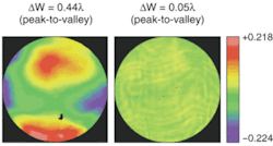
The initial 0.44λ (peak-to-valley at 1053 nm) transmitted-wavefront error in the desired 21-mm clear aperture of the 25.4-mm-diameter Nd:YLF laser rod was reduced to 0.05λ after several MRF iterations (see Fig. 2).
Several issues associated with wavefront-correcting Nd:YLF laser rods were identified. First, the measured transmitted-wavefront distortion is different for linearly polarized light aligned with the c axis (gain at 1047 nm) or a axis (gain at 1053 nm). As a result, MRF corrections must be performed for the specific polarization required for laser operation. Second, the transmitted-wavefront quality of MRF-corrected laser rods depends on the alignment of the laser rod because the MRF corrections are applied on a single endface to correct for bulk inhomogeneities distributed throughout the laser rod. As a result, the operational alignment must match the one used for the interferometric measurements taken to calculate the MRF correction. Similarly, the orientation of the laser rod during the interferometry measurements of successive MRF iterations must be repeatable for the corrections to converge. This alignment repeatability ultimately limits the residual wavefront error that can be achieved.
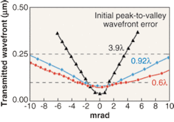
The peak-to-valley transmitted-wavefront error was measured for three laser rods before MRF correction; its dependence as a function of rod orientation after the wavefront correction was also measured (see Fig. 3). Transmitted-wavefront errors of better than λ/4 (peak-to-valley) were obtained for angular misalignments not exceeding ±10 mrad for two of the laser rods, which were of typical form, while a narrower range of ±4 mrad was observed for the third rod, which started with a significantly poorer initial wavefront. Given that alignment accuracy better than ±1 mrad can be achieved by standard alignment techniques, diffraction-limited performance is expected.
Performance with MRF-corrected laser rods
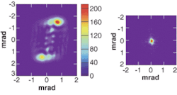
When the CLARA was operated with uncorrected Nd:YLF laser rods, the largest beam that could be amplified without damaging downstream optics was a 10-mm round beam. The measured far field shows a large angular divergence that is unsuitable for pumping phase-matched processes like OPCPA (see Fig. 4). A corresponding CLARA far-field measurement using two MRF-corrected laser rods demonstrates the greatly improved divergence of this beam. The nearly diffraction-limited performance achieved meets the requirements for efficient OPCPA pumping. In addition, the wavefront improvements realized in these laser rods allowed operation of the laser with beams as large as 17-mm in diameter, which greatly increased the energy extraction.
Magnetorheological finishing allows diffraction-limited performance from large-aperture Nd:YLF laser rods. The MRF technique holds promise for additional applications, such as precompensating thermal aberrations and postprocessing large-area laser crystals. Because thermal lensing is a low-order error to the transmitted wavefront, static MRF corrections to laser-gain elements could easily precompensate for these errors without requiring any other elements in a laser cavity. Transmitted-wavefront distortions observed at the boundaries of large-area laser crystals that are produced by diffusion bonding of smaller-aperture elements should also be correctable.
JONATHAN ZUEGEL andVINCENT BAGNOUD are with the Laboratory for Laser Energetics, University of Rochester, 250 E. River Rd., Rochester, NY 14623; e-mail: [email protected] .TARA CORSO, PHIL DREW, and GREGORY J. QUARLES are with VLOC, 7826 Photonics Dr., New Port Richey, FL 34655. PAUL DUMAS, JAMES T. MOONEY, and STEPHEN D. O’DONAHUE are with QED Technologies, 1040 University Ave., Rochester, NY 14604.
REFERENCES
1. A. Dubietis et al., Opt. Commun.88(4-6) 437 (1992).
2. D. Strickland, G. Mourou, Opt. Commun. 56(3) 219 (1985).
3. I. N. Ross et al., Opt. Commun.144(1-3) 125 (1997).
4. J. Collier et al., Appl. Opt. 38(36) 7486 (1999).
5. M. J. Guardalben et al., Opt. Express11(20) 2511 (2003).
6. A. V. Okishev, W. Seka, IEEE J. Sel. Top. Quantum Electron.3(1) 59 (1997).
7. M. D. Skeldon, Rev. Sci. Instrum.71(9) 3559 (2000).
8. A. V. Okishev et al., TOPS (Optical Society of America, Washington, D.C.), 73, 365 (2002).
9. J. M. Auerbach, V. P. Karpenko, Appl. Opt. 33(15) 3179 (1994).
10. A. Babushkin et al., SPIE Proc. 3492, 939 (1999).
11. D. Golini et al., SPIE Proc. CR67, 251 (1997).
12. S. D. Jacobs et al., Finishing of Advanced Ceramics and Glasses (The American Ceramic Society, Westerville, OH), 102, 185 (1999).
13. D. Golini et al., Opt. Photonics News 12(10), 20 (2001).


