Lit-appearance modeling uses ray tracing and visualization
The field of illumination design is growing rapidly, often using lens designers and requiring them to hone their design skills “on the job.” Transfer efficiency and agreement with the desired illumination distribution are the typical goals in the design of these systems. The secondary goal of reducing production costs, however, often plays a determining role in the final design. A tradeoff in meeting design metrics such as uniformity and efficiency is allowed if the cost is held low while providing a desired “look.” The “correct look” is required in both unlit and lit states, which is often called unlit appearance and lit appearance, respectively.
Unlit appearance is typically obtained through visualization software that renders the illumination system when lit by external light sources. These rendering packages are often integrated into CAD software, so the designer can quickly iterate through design changes until the desired unlit appearance is obtained. Algorithms based on simplified ray tracing and/or radiosity-analogous to scatter models found in optical-design software that use the bidirectional-scattering-distribution function (BSDF)-are used to accomplish this task.
Optical-design software can also provide some level of visualization, but the accurate ray-tracing techniques used therein limit the utility in such algorithms-the computation time is too long because of the overhead required to deliver their inherent accuracy. In addition, these visualization tools have not been an area of important development because there is no need for optical-design software to upgrade routines that have already been well developed by the visualization community.
Either simplified rendering through visualization software or accurate ray tracing from optical-design software can be used to model lit appearance. It has been found, however, that ray tracing using optical-design software is required for effective rendering of the lit appearance. Basic rendering methods often do not match the lit appearance because of source-model approximations and ray-tracing simplifications. A compromise is a logical solution-the optical-design software is used to trace the rays from the source in the illumination system, while visualization software is used to provide the final step for the lit appearance.
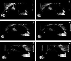
FIGURE 2. Lit appearance of a lightpipe is shown for six observation angles ranging from -20º to +30º (top to bottom), inclusive, with a step size of 10º.
TracePro 3.2, optical-design software available from Lambda Research, integrates LightWorks, the photorealistic renderer developed by LightWork Design (Sheffield, England). This feature provides a quick way to model the lit appearance of the illumination system prior to costly fabrication. In fact, iterations that include design modifications, ray tracing, and rendering provide a study of the trade space between objective requirements, such as efficiency and uniformity, and subjective ones, such as the “look” in a lit state. This module can be used to display the unlit appearance without the use of other software-leaving the rendering to the dedicated visualization programs and the ray tracing to the optical-design programs.
Lit-appearance modeling includes the characteristics of the observer. A typical human observer, for example, who has a log response to incident flux, is assumed to have the ability to observe 2.4 log orders without saturation, and saturation can be included by setting the minimum or maximum illuminance value (lumens/m2 = lux). In addition, while the human eye detects the illuminance of a given scene, we respond to the luminance (lux per steradian = nit). It is impossible to display the luminance of a lit object with a single picture, but a series of pictures can be generated to show the lit appearance over a range of observation angles. These pictures can be joined to animate the lit appearance of a system-much as we would see it in our everyday world.
Lit-appearance model of a lightpipe
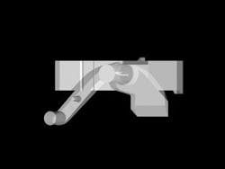
Nearly one million rays were traced from the filament through a lightpipe (see Fig. 1). Within the rendering engine these rays were binned over a set of capture angles, a log response of 2.4 was assumed, and spatial blending (that is, averaging) was implemented to diffuse the appearance (see Fig. 2). Certain parts of the lightpipe, such as the power/volume-button indicator were observable over the entire range, but other parts of the lightpipe were only observable from certain angles because of the design of the lightpipe. For the regions observable over limited angular ranges, this light emission is actually leakage, or in other words, a loss of efficiency. This leakage is allowable because of the objective requirements being met with the chosen source. A lower flux-output source would require more design time to increase efficiency.
The handshaking required between the ray-tracing and the rendering engines does require a level of attention and overhead. Is there a method to determine the lit appearance of an illumination system without transitioning between the various modules? Yes, but it requires an observer to be placed within the optical system. Realize that lit-appearance modeling integrates a nonimaging illumination system and an observer to image it. Thus, a model of the human eye is included with the lightpipe model and rays that strike the retina are used to form the lit appearance model at that position in space.
This setup is seemingly simple; however, one must not forget that in a ray-trace model only a few rays are likely to pass through the pupil of a distant eye. The answer is to assign an importance edge to the emission surfaces of the system. This importance edge is placed at the pupil so that rays are only scattered from the optic to it. Scattering can include any measured BSDF profile, such as the three-axis polish for injection-molded plastic that was assigned to the lightpipe.
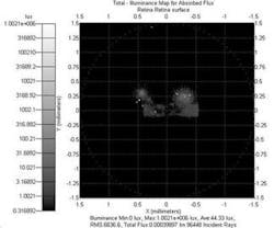
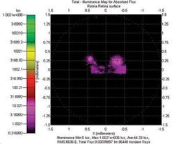
FIGURE 3. The view from the 0º observation angle is presented in gray scale, as the eye would observe (top), and in false-color (bottom).
Results from TracePro for an observation angle of 0degrees for this configuration indicate curvature of the retina, which can be compensated by software; the log response of the eye can be included in the model; and the focus of the eye can be set for different object distances (see Fig. 3). Finally, a series of eyes including their respective importance edges can be located at different positions, and a single large ray trace can be performed with scattered rays sent to each distinct pupil-importance edge. The resulting model would be analogous to Fig. 2.❏
null
R. JOHN KOSHEL is a senior staff engineer at Lambda Research, 8230 East Broadway, Suite E2, Tucson, AZ 85710; e-mail: [email protected].


