JEREMY GOVIER
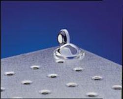
For more than two decades optical engineers have appreciated the advantages of incorporating aspheric surfaces into optical designs. Aspheres can improve performance of a low-f-number lens, for instance, or of a lens in which weight constraints limit the number of optical elements-but difficulties in manufacturing and related metrology have hindered their use (see Fig. 1). In the last decade, however, advances in asphere manufacturing and testing have increased the feasability of using aspheres in optical design. Although some manufacturing and testing challenges remain, these hurdles can be overcome with some added care in the design process.
Using aspheres in design
Today’s optical-design software allows designers significant design freedom to use aspheric terms on every surface in an attempt to converge the optimal design solution. The software can easily and quickly produce a result for an asphere that will improve a lens design, but the quick and easy approach or the indiscriminate use of all degrees of freedom may yield an element that either can’t be manufactured or is expensive to produce. Such designs either get cancelled before manufacturing or the specifications are reduced to eliminate the asphere.
This doesn’t have to happen, however. By limiting the software’s freedom, the designer can find only solutions that are manufacturable. Two aspheric surfaces are typically needed to provide sufficient performance-one near the stop to correct for the spherical aberration, and one away from the stop to correct for field-based aberrations.
Adding appropriate constraints and pushing the design to the optimum solution allows a designer to quickly turn a difficult part into a viable solution. To properly constrain the software, however, the designer must know how the part will be produced and what concerns manufacturing will have.
Manufacturing aspheres
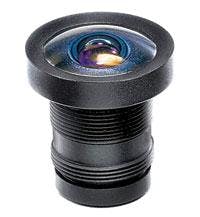
Manufacturing technologies for aspheres have improved significantly over the last decade. Very accurate optical surfaces can be molded with exceptional quality, but tooling costs are still rather high compared to conventional optics, which limits the economical use of molding to high volumes. Typical mold costs range from $25,000 to $50,000 depending on the size and number of cavities, with manufacturing volumes typically on the order of hundreds of thousands of pieces. Molded aspheres are used primarily in commercial optics such as digital cameras that are produced in volumes reaching hundreds of thousands or even millions of units (see Fig. 2).In terms of machining, diamond turning has long been an option for crystalline materials and nonferrous metals, but new methods like high-speed computer-controlled small-tool or disc grinding have enabled machining methods to produce aspheric surfaces in glass and other optical materials. Computer-controlled high-speed grinding can fine-grind an aspheric shape by using the edge of a disc-grinding tool and tracing out the aspheric shape as the lens spins axially. This does not yield an optically smooth surface, so an additional polishing step is necessary. Typically, polishing is done with a soft conforming tool that produces optical smoothness while maintaining the ground shape.
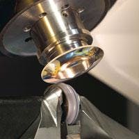
In addition, magnetorheological finishing (MRF) can be used to correct and smooth a finished asphere, or to induce a mild aspheric departure in a spherical polished lens (see Fig. 3; see Laser Focus World, July 2001, p. S5). The MRF method uses a fluid that changes shape and consistency when a magnetic field is applied, which allows the computer to vary the removal rate of the glass while it’s polishing different areas. Diamond turning has been used for small-volume infrared optics for years, and surface roughness has limited its practical use on visible optics. But MRF can also finish a diamond-turned optic to remove high-frequency diamond-turning marks, which makes diamond turning more useful for visible optics. It is important to remember, however, that MRF is a finishing process: it requires a polished part such as a machined, molded, or a polished sphere.All of these machining methods are computer controlled and rely on a feedback loop to adjust the motion across the part based on monitoring the surface being finished. To achieve the designed shape, accurate metrology is required for these methods to work properly.
Metrology of aspheres
Interferometry has been the standard means of testing conventional spherical optics since Newton’s time. For aspheres though, interferometry is much more complex. High-volume manufacturing facilities have long used computer-generated holograms (CGHs) to produce the reference wavefront, but the significant tooling expense effectively restricts the use of CGHs in low-volume situations.
New developments in commercial interferometry, such as the use of high-resolution cameras and the stitching of subapertures may eventually allow analysis of larger departures from spherical wavefronts but these technologies are currently limited to relatively small departures from spherical surfaces. Nonetheless, each year more applications become viable. Also, the promise of noncontact aspheric metrology, while not fully realized, is coming close to fruition. Finally, surface profilometers have become more accurate and now give accurate profiles without special tooling.
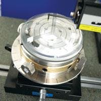
Profilometers are relatively fast so they are more viable for small-volume testing. It is important to note, however, that they give profiles, not surface measurements, so they only contain data from a single plane. Several profiles are needed to get an accurate map of the surface. Using a profilometer is best when it can be assumed that only rotationally symmetric errors are present in the part (see Fig. 4).Cost drivers
The cost drivers differ for molding or machining aspheres. Molding drivers include quantity, accuracy, thickness, and surface accuracy. Tooling costs can make molding prohibitively expensive for anything less than high-volume manufacturing. Tooling costs also increase as the required accuracy of the shape is increased, due to the need for iterative correction of the mold-several iterations can be required to get the mold to the final shape. The high temperatures involved in molding can cause significant shrinking when a lens cools. The larger the coefficient of thermal expansion and the greater the difference in thickness from the center to the edge of the part, the more the lens will deform when it cools.
The main cost driver for machining an asphere is machine time, which is affected by accuracy and size. For most methods, the greater the departure from a sphere the more machine time is required and the more difficult the testing. The desired accuracy of the surface also affects machine time, because finishing with MRF may be necessary to get a high-quality surface. Finally, the size of a lens also affects the machining time-a 4-in.-diameter lens takes longer and is more expensive than a 1-in. lens. Tooling is usually only an issue during testing, so economy of scale is not as important for machining as it is for molding.
The optical designer must also consider the limits of machining. Machining lenses with a short localized radius is often a problem, for instance, because the shortness of a concave radius is limited by the limits of tool sizes. A slope change from convex to concave will make a part difficult (maybe impossible) to machine, depending on the rate of slope change. Very small parts can be impossible to machine because of the relative size of the tool.
The best time to reduce the cost of a part is during design. If designers account for the volume and cost drivers by adding the appropriate constraints to the software, manufacturing can produce a part that meets the requirements at a minimized cost.
If parts will be molded, the designer can select glasses with low melting points and low thermal expansion to minimize shrinkage and consequent costs. Controlling the difference between the center thickness and the edge thickness of the part will also reduce deformation due to shrinkage (see “A most significant cost factor,” p. 70).❏
JEREMY GOVIER is director of design services at Edmund Optics, 101 East Gloucester Pike, Barrington, NJ 08007-1380; e-mail: [email protected]; www.edmundoptics.com.
A most significant cost factor
Controlling the degree of departure from a sphere is often the most significant cost issue when machining an asphere. Designers must consider the departure at the edge of the lens. Lens-design software, based on where it traces rays, generates an equation describing the asphere. When an asphere is included in an optical design, more rays must be traced than is typical in an all-spherical design-meaning more field points must be added and the grid density of the rays traced must be increased for each field point.
These points within the clear aperture of the lens define the equation generated by the software-but manufacturing has to make the shape all the way to the edge. Many equations describe identical sags over the clear aperture, yet very different sags outside the clear apertures. It is not unusual for an aspheric equation to have a slope inversion that is outside the clear aperture, but within the actual diameter of the lens. These dramatic changes from a best-fit sphere can cause major problems in manufacturing.
Tracing rays outside the clear aperture, but within the diameter of the part, can correct this problem. To do this, field points are added outside the actual field of view and the aperture stop diameter is increased slightly. When optimizing, less weight is put onto these new field points so they do not dramatically change the correction in the part. In addition, the software can calculate the best-fit sphere to the aspheric equation and force the sag outside the clear aperture to be similar to the best-fit sphere’s sag. Almost all the design codes allow for the surface sag at any height to be used as an operand in the merit function.
The added field points and larger aperture stop will also help to reduce the design’s sensitivity to lens decenteration, which causes rays to hit outside of the clear aperture. Adding more control over the surface outside the clear aperture reduces the negative effects of decentering.
As in the case of molded optics, placing the asphere in the design so it has a smaller diameter can also reduce the machining time of the part. The smallest radius that can be cut into the mold restricts how small a mold can be made. Optimal mold sizes tend to be between 10 and 25 mm.


