POSITION SYSTEMS: Applications dictate gimbal selection
SCOTT SCHMIDT
Precision motion-control systems have found widespread use in a number of broad markets. Each application requires certain critical motion performance specifications that define the motion technology or technologies best suited for the job. In many cases, one technology becomes an obvious choice. In other applications, two or more competing technologies may deserve consideration. The choice between direct-drive and gear-driven gimbals presents just such a comparison based on the application.
Gimbal performance criteria
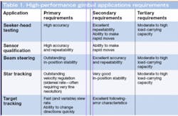
Depending on the application, a number of key performance characteristics are of primary importance when selecting a positioning system (see Table 1).
Accuracy is defined as the difference between the actual position in space and the position as determined by an independent measurement device. Positioning-stage accuracy is influenced by the feedback mechanism (inductosyn, resolver, rotary encoder), and drive mechanism (ball screw, lead screw, direct-drive motor).
Repeatability is the range of positions attained when the system is repeatedly commanded to one location under identical conditions. Unidirectional repeatability is measured by approaching the point from one direction, and ignores the effects of backlash or hysteresis within the system. Bidirectional repeatability measures the ability to return to the point from both directions.
Resolution, or the smallest possible movement of a system, is also known (somewhat misleadingly) as step size. The feedback device determines resolution, and in some cases, theoretical resolution can exceed practical resolution. For example, in a ball-screw-based positioning system, a theoretical resolution of 4 nm can be obtained by combining a 4-mm/revolution screw, 1000-line encoder, and a ×1000 multiplier. The actual motion system will never be able to make a single 4-nm step due to friction, windup, and mechanical compliance.
In-position stability is the system “jitter” about a stable, controlled position being maintained by the controller and rotary stage. This attribute may be influenced by mechanical compliance in the system, as well as servo tuning details and amplifier (linear versus pulse-width modulation) capabilities.
Velocity regulation, or the ability of a controller and stage to closely follow a commanded velocity profile, is expressed as either a peak-to-peak or as a root-mean-squared value. Precise definition of a timescale for this measurement is crucial. The required velocity (often termed sidereal rate) can be extremely low, requiring high-resolution systems to avoid “staircase” motion effects as the gimbal tracks from one encoder position to the next over a relatively long period of time.
Finally, following error is defined as the difference between the commanded and actual positions while the axis is moving.
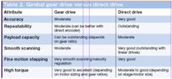
Although these basic motion metrics define gimbal system performance, other values are just as important. Tightly influenced by motor holding torque, gear ratios, and bearing strength, the load capacity—the total mass that the gimbal structure can hold or support and also effectively actuate—must be considered. Along with this, the required speed, range of motion, and duty cycle, as well as the ability of the gimbal to withstand severe environmental conditions such as high condensing humidity, extreme temperature ranges, vacuum, or clean-room applications, are of critical importance. And of course, the footprint of the gimbal must be taken into account, considering that often the gimbal must fit into a predefined location such as on an optical table or in a vacuum chamber. Motor size and orientation, as well as brake and gearbox footprints, can influence this attribute. Although piezo-driven and belt/chain-driven positioning solutions are considered for some unique applications, gear- and direct-driven systems are almost universally considered. Both gear and direct-drive gimbal technologies have attributes that offer specific advantages for particular uses (see Table 2).Gear-driven gimbals
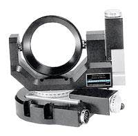
Gear-driven gimbals utilize a precision gear and matched worm-drive mechanism to achieve rotary motion in the azimuth (AZ) and elevation (EL) axes (see Fig. 1). Design and implementation flexibility are achieved using a rotary motor to drive the worms, allowing the designer to choose stepper versus servomotor and different types of encoders. The different motor choices also result in a greater range of controller and drive choices, and can easily accommodate fail-safe braking options. The system can be tailored to enhance system speed (low ratio) or drive capacity (higher ratio) by choosing a specific worm/gear ratio.Geared gimbals usually represent a cost-effective choice. The mechanical linkages used within geared gimbals can offer very good in-position stability. The motor is not directly driving the AZ or EL axis for either drive, which to some extent mutes the servo-dithering motion from coupling through the system and manifesting as excessive jitter. Perhaps the most obvious advantage offered by this solution is in the gearing itself. Higher load capacities, as well as the ability to tolerate somewhat unbalanced loads (limited by stresses in the gear teeth), is a natural benefit, while excellent overall system stiffness is also achieved.
Although the load-multiplying effect of a geared system is attractive for greater load-handling capability, some specifications suffer. Backlash effects (the portion of commanded motion that produces no change in position upon reversal of travel direction—caused by clearance between elements in the drive train) can degrade the bidirectional repeatability of the gimbal. The mechanical compliance in this style of drive train essentially prohibits quick motions and sharp direction reversals as the constituent rotary stages waste most of the motion efforts in overcoming hysteresis (reversal error) and suffer from the mechanical abuse these types of moves would impart to the gears and linkages. For applications requiring highly repeatable and accurate motion in more than one direction of travel, such as target tracking and some beam-steering applications, this deficiency can rule out the use of worm-gear-driven gimbals.
These issues can be partially solved by using an external encoder installed close to the axis of rotation, but this addition sacrifices one geared-gimbal advantage: low relative cost.
Also, thermal expansion effects, and the corresponding degradation of system accuracy and repeatability, will be much more dramatic with worm drives because of their asymmetric nature and dissimilar materials used in their structures. Wear, lubrication, and maintenance issues must be considered for worm-gear-driven gimbals to ensure proper lubrication of the gear train over the lifetime of the gimbal as the worm-gear teeth wear.
Two applications that are best suited to gear-driven gimbals are large-optic beam steering and general laboratory duty. Large optical components require the positioning system to have a large load-carrying capacity, with limited acceleration and velocity requirements. The ability to use an auxiliary encoder with gear-driven gimbals mitigates backlash to some extent, while providing high load-bearing capability and excellent in-position stability. These attributes are also important in the laboratory, where the high gear ratios and excellent stiffness of the gear-driven gimbal can meet a wide range of laboratory positioning requirements.
Direct-drive gimbals
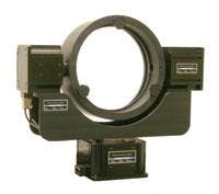
While gear-driven gimbals rely on a mechanical drive train to achieve motion and the resulting system stiffness, direct-driven solutions couple the stages of the AZ and EL axes to the rotary motor itself (see Fig. 2). Although any type of rotary motor can be integrated into such a gimbal structure, brushless motors are the most common. The absence of gear trains and mechanical couplings eliminates position errors caused by hysteresis, windup, and backlash. As a result, direct-drive achieves higher accuracy than worm gears.An accuracy-influencing factor in direct-drive gimbal systems is the directly coupled feedback device. Rotary encoders are typically used to track the position of each axis, and inductosyns and resolvers can be used to offer a higher degree of environmental ruggedness and stability. Current encoder technology can achieve subarcsecond accuracy, allowing the resulting gimbal axes to have accuracy values less than 10 arcseconds. The directly coupled feedback devices used in these gimbals allow bidirectional repeatability values of around 5 to 10 arcseconds, compared to ranges that are typically at least twice that for gear-driven axes. Because the stages of direct-driven gimbals do not have the mechanical windup and backlash of their gear-driven counterparts, quick moves and sharp direction reversals can be made. Slew rates of 300°/s or more are possible, compared to a maximum velocity of perhaps 60°/s for worm-gear gimbals.
Despite the inherent motion performance advantages of direct-drive gimbals, some drawbacks to this technology do exist. Perhaps the most basic limitation of direct drive is the allowable aperture of the motors housed within them. Rotary gears can have an almost arbitrarily large through-hole, but the integral motors around which direct-drive stages and gimbals are constructed essentially limit the aperture size to about 100 mm in all but the most unusual designs. This constraint likely would not be confining for most routine applications, but could be limiting for those that require clear apertures through the base/azimuth stage for some specialized beam-steering or polarizer applications. Other disadvantages of direct-drive systems are merely the inverse of gear-driven features: load-bearing capability can be less than what might be achieved with gear-driven solutions and direct-drive gimbals are less able to accommodate unbalanced loads because the motors would constantly need to be engaged without the aid of a gear system.
Applications that benefit from the high accuracy, ability to make rapid moves, fast (and variable) slew rate, and excellent following-error characteristics of direct-drive gimbals are missile-seeker-head testing, sensor qualification, beam steering, and star and target tracking.
Scott Schmidt is senior applications engineer in the Positioning Systems Division of Aerotech, 101 Zeta Drive, Pittsburgh, PA 15238-2897; e-mail: [email protected]; www.aerotech.com.


