The world of computer-aided design (CAD) in manufacturing and engineering has gradually incorporated simulation tools for modeling mechanics, machining, thermal effects, motion dynamics, vibration, and acoustic phenomena. Optical simulation has lagged behind these other areas, but is now entering the realm of full CAD capability.
The inability of mechanics and optics to interact in the same software has led to numerous design process limitations. For instance, altering something in the optics meant that the mechanics had to be rethought from the beginning, which tended to impede the intuitive flow of design processes. Also, product design alternatives were often limited because software development wasn’t able to keep up with the latest advances in industrial production capabilities. Industrial machines have been able to produce free-form optical components for at least 30 years, for example, but optical designs have not followed suit because optical-design software was only able to simulate spherical and aspherical lenses.
The optical-design community has approached these difficulties over time by progressively integrating optical software into CAD essentially at three levels. At the first level, stand-alone optical software simulates sequential or nonsequential optical propagation phenomena, such as photometry and radiometry results, ray tracing, aberration results, spot diagrams, and modulation transfer functions (MTFs). The simulations are performed without any interaction with other physical parameters, allowing optical calculation and optimization to be done independently of the surrounding mechanics.
After having designed and optically validated systems at this level of integration, optical engineers can deliver their design to mechanical engineers with CAD import and export capabilities, but optical engineers cannot directly rework their designs and generally can’t interact easily with other production departments.
At the second level of integration, mechanical tools have been integrated into optical-design software. With these tools, optical engineers benefit from direct optomechanical design capabilities, and the mechanical environment is developed around the optics. Data import and export are still required. Designers cannot use specific CAD software tools, however, which still impedes interaction between optics and other disciplines.
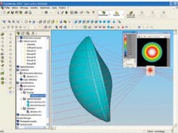
FIGURE 2. Direct use of the CAD modeler to create optical shapes offers the possibility of creating nonsymmetric systems with free-form shapes that might be used, for instance, in miniature optical systems.
At the third and current level, nonsequential propagation simulation has been supplemented with luminance, illuminance, colorimetry, analysis, and optimization capabilities in optical-design software that is fully integrated in a CAD program, enabling calculation of optical parameters directly in CAD. One of the primary challenges in achieving this capability was to design aspherical lenses in mechanical CAD software with the same accuracy as in optical software.
Adding an aspherical surface feature makes it relatively easy to build spherical lenses in CAD because the sphere is one of the common surfaces in CAD programs. There are no traditional CAD features corresponding to aspherical surfaces, however. So while it is possible to use nonuniform rational B-spline (NURBS) surfaces to build an aspherical surface, the approximation required to simulate aspheres offers resolution, at best, on the order of 1 µm, which is not fine enough for optical calculations. Sequential optical propagation, for instance, requires resolution several times smaller than the wavelength of light for calculating points of intersection of between rays and surfaces.
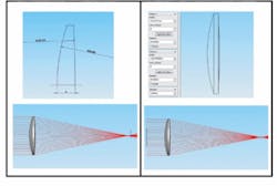
Consequently, our first step in developing OptisWorks optical-design software that is fully integrated into CAD software from SolidWorks (Concord, MA) was to create an aspherical surface feature in the CAD software using mathematical definitions. A property page was added to allow users to input curvature radius, conic constant, and aspherical coefficients. This enabled a spline surface to be built from the aspherical surface definition and used for display purposes in the CAD software (see Fig. 1).
The second step was to use the same mathematical definitions for the optical-design simulation and analysis. SolidWorks allows us to store a dedicated feature used for ray-tracing calculation. When we calculate the intersection of a ray with a surface, the aspherical coefficients corresponding to the surface are used to compute the point of intersection.
Because it is based on mathematical definitions, the added feature is able to generate any kind of geometry, not just aspheres. Free-form optics can also be simulated with the CAD modeler, with sufficient accuracy for simulating and validating optical and optomechanical design features using traditional optical parameters directly in the CAD interface.
One application for this kind of feature is the miniaturization of optical systems. We can imagine, for instance, that telecentric systems could be replaced by nonsymmetric systems with free-form shapes (see Fig. 2). This kind of innovation would allow designers to move away from standard or predefined product shapes and sizes.
Because calculation accuracy is only limited by computer precision, optical intersections and paths are calculated with the same precision as with traditional stand-alone optical-design software. Moreover, the integration of optical design in CAD software enables the use of layout sketches for optical designs, enabling optical properties to be modified as necessary using another layout sketch to modify the appropriate parameter in a solid model.
JEAN-BAPTISTE HAUMONTÉ is the marketing manager and JEAN-CLAUDE VENTURINO is an optical design expert at Optis, BP 275, ZE de La Farlède, 83078 Toulon Cedex 9, France; e-mail: [email protected]; www.optis-world.com.

