UV SOURCES: World’s largest laser to generate powerful ultraviolet beams
Expected to be completed in 2009, the National Ignition Facility will enable the demonstration of a fusion event within a laboratory and new science in the areas of astrophysics and high-energy-density science.
CAMILLE BIBEAU, PAUL J. WEGNER,and RUTH HAWLEY-FEDDER
The National Ignition Facility (NIF) at the Lawrence Livermore National Laboratory (LLNL; Livermore, CA) will begin ignition experiments in 2010, ushering in a new era of high-energy-density physics research.1 The primary missions of NIF include weapons-stockpile stewardship for national security, performing research for fusion energy, and unfolding new regimes in basic and applied science. More than 85% complete, the NIF spans the length of two football fields and will house 192 laser beams, each measuring 0.4 m in aperture.
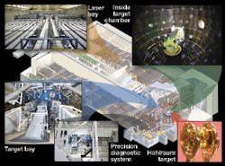
During an ignition event, all 192 beams will simultaneously converge on a 10 m diameter target chamber holding a fusion target the size of a dime (see Fig. 1). Implosions of the target work far better at shorter laser wavelengths, which generate fewer hot electrons that can preheat the fusion target fuel and make it harder to compress. As a result, the NIF is designed to operate at the third-harmonic wavelength of its Nd:glass amplifiers, delivering up to 1.8 million joules of ultraviolet energy to the target in a few billionths of a second.
During an ignition shot, temperatures in the target will reach tens of millions of degrees and pressures will exceed one billion atmospheres, similar to conditions inside the Sun and stars. When completed, the NIF will be the largest ultraviolet laser in the world, and its performance has already surpassed energy records. In December 2005, 152 kJ of IR energy was generated with only eight beams, exceeding the highest IR energies ever achieved on a fusion-class laser.
NIF final optics
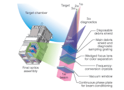
The NIF layout utilizes a multipass architecture for each of the 1.053 µm (1ω) single beamlines (see Fig. 2). These amplified beams are transported in 2 x 2 quad arrangements to the target chamber where final optics assemblies convert the frequency of each quad of beams to the third harmonic (3ω) and focus them onto the target. Each final optics assembly contains four integrated optics modules that incorporate beam conditioning, frequency conversion, focusing, diagnostic sampling, and debris-shielding capabilities into a single compact assembly (see Fig. 3). The fused-silica final focus lens is a wedged design that provides color separation at the target via lateral dispersion. As beam pointing is adjusted into the chamber for different targeting scenarios, precision actuators are used to adjust lens focus and maintain absolute angular alignment of the frequency conversion crystals.
FIGURE 3. The final optics assembly outside the target chamber contains a phase plate for beam conditioning, KDP and KD*P crystals for frequency conversion, a fused-silica lens for focusing, and two plates for diagnostic sampling and debris shielding (fused silica and boro-float glass).
The NIF frequency converter is designed to give optimal performance at the design point of 1.8 MJ and 500 TW. Efficient operation at this level requires precise control of tolerances; crystals must be tilted to microradian accuracy, temperature must be controlled to a few hundredths of a degree, and wavelength must be set to a hundredth of an angstrom. Crystal surfaces must also be finished to nanometer smoothness so that the high-power 3ω laser pulse will have the required beam quality. The two types of crystalline materials used in the NIF frequency converters are potassium dihydrogen phosphate (KDP) and deuterated potassium dihydrogen phosphate (KD*P), both with dimensions of 42 x 42 cm. The KDP functions as a Type I doubler, and the KD*P is used for Type II tripling.
Third-harmonic generation
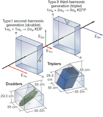
Third-harmonic generation for NIF is accomplished by a sequential application of collinear sum-frequency mixing in two nonlinear optical crystals (see Fig. 4). A beam at the fundamental laser frequency enters the doubling crystal in which two-thirds of the incident light is converted to the second-harmonic frequency via degenerate sum-frequency mixing (2ω = 1ω +1ω). The copropagating second harmonic and residual fundamental beams that emerge from the doubling crystal enter the tripling crystal, where a third-harmonic beam is created by sum-frequency mixing of the fundamental and second-harmonic beams (3ω = 2ω + 1ω).
FIGURE 4. Third-harmonic generation is accomplished using two different crystals. Type 1 second-harmonic generation with KDP is followed by Type II third-harmonic generation with KD*P. Beam polarization directions are shown in relation to the crystalline c-axes.
The efficiency with which energy is transferred from the fundamental wave to the harmonic waves is dependent upon several parameters, of which phase-mismatch is particularly important. Phase-mismatch is defined as the difference between the k-vector of the output wave and the sum of the k-vectors of the input waves. Maximum energy transfer from the input waves to the generated waves occurs when the phase-mismatch is zero. This condition is usually achieved in nonlinear optical crystals by using the birefringence of the crystal to balance the effects of normal dispersion. This leads rather naturally to two types of phase matching: Type I, in which the input waves have the same polarization inside the crystal, and Type II, in which the two input waves are orthogonally polarized.2
The NIF frequency converter uses Type I second-harmonic generation followed by Type II third-harmonic generation, a selection made on the basis of angular and polarization sensitivities and the sizes of the crystal boules needed to produce frequency-converter plates of the appropriate size. In this scheme, the critical 2:1 mix ratio of 2ω to 1ω energy needed for efficient frequency tripling is achieved by angularly biasing the Type I doubler a few hundred microradians from exact phase matching.3 As a result, the Type I/Type II design is more angularly sensitive than a comparable Type II/Type II design, but has the advantage of being quite insensitive to depolarization.
Crystal growth and fabrication
During the past ten years, technologies have been successfully developed to quickly grow large, high-quality KDP crystalline boules to the sizes needed for fabrication of the NIF optics. The fast-growth method currently used was pioneered in Russia.4 The large KDP crystals currently in use in the NIF were grown at LLNL and two commercial vendors: Cleveland Crystals (Highland Heights, OH) and the former Inrad (now Photonic Products Group; Northvale, NJ). To minimize stimulated Raman scattering (approximately 2x) from third-harmonic generation 70% of the hydrogen is substituted with deuterium.5
While the growth of crystal boules for producing NIF crystal optics can now be considered an established production process, the production of finished crystals to meet all NIF specifications is a relatively recent accomplishment. The KDP and its deuterated analog are difficult materials to fabricate in the large aspect ratios required for NIF. The high water solubility of KDP requires nonaqueous processing. In addition, KDP is very thermally sensitive-a temperature change of approximately 2°C is sufficient to induce fracture in the presence of a flaw of less than 100 µm in size. Both faces of both crystals are SiO2 sol-gel antireflection coated. The input face of the doubler is coated for maximum transmission at a wavelength of 1054 nm. The output face of the doubler and the input face of the tripler are coated for maximum transmission at a wavelength of 700 nm, which provides very high transmission at 1054 and 527 nm. The exit face of the tripler is coated for maximum transmission at 351 nm.
Performance
The frequency-converted performance of the NIF laser has been tested and verified in a series of experimental campaigns referred to as NIF Early Light.6 These campaigns, conducted between November 2002 and September 2004, included the first NIF target experiments utilizing one quad of beams on the target chamber, as well as detailed single-beam laser characterization experiments executed with the NIF Precision Diagnostic System (PDS). The PDS is a 6000 ft2 facility inside the NIF building incorporating a single-beam version of the final optics assembly (one integrated optics module) and a comprehensive suite of input and output beam diagnostics that allow a far more complete evaluation of the laser performance than can be achieved on the target chamber. A roving mirror assembly is used to select specific beams exiting the laser amplifier and direct them to the PDS for individual diagnosis.
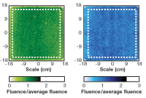
FIGURE 5. Color-enhanced near-field beam images of high-energy 2ω (left) and 3ω (right) shots were obtained in the NIF precision diagnostics system. The contrast ratios (standard deviation of fluence/average fluence) within the outlined aperture are 0.13 and 0.17 for the 2ω and 3ω beams, respectively.
The PDS campaigns successfully demonstrated 3ω operation at energy levels up to 10.4 kJ in a flat-in-time 3.5 ns pulse (equivalent to 2 MJ for full NIF, meeting the NIF 1.8 MJ design requirement). Frequency doubling was also tested by removing the tripling crystal and reducing the doubler tuning angle offset to approximately 120 µrad to better optimize the phase-matching for second-harmonic generation; 2ω energies up to 11.4 kJ/beam in a flat-in-time 5 ns pulse were produced in this configuration. Near-field images for the highest energy 2ω and 3ω shots, both demonstrating excellent beam quality at record harmonic energies from a single laser aperture (see Fig. 5).
ACKNOWLEDGMENTS
The authors would like to acknowledge L. Jeffery Atherton, Jack H. Campbell, Christopher A. Haynam, Thomas G. Parham, Bruno M. Van Wonterghem, and the NIF development, engineering and operations teams of Lawrence Livermore National Laboratory and Jeff Luken at Cleveland Crystals Inc. for their significant scientific and engineering contributions. This work was performed under the auspices of the U.S. Department of Energy by University of California, Lawrence Livermore National Laboratory under Contract W-7405-Eng-48.
REFERENCES
1. G.H. Miller, E.I. Moses, C.R. Wuest, Nuclear Fusion 44, S228 (2004).
2. J.E. Midwinter, J. Warner, Brit. J. Appl. Phys. 16, 1135 (1965).
3. R.S. Craxton, IEEE J. Quantum Electron. QE-17(9) 1771 (1981).
4. R. Hawley-Fedder et al., Proc. SPIE 4102, 152 (2000).
5. J.H. Campbell et al., ICF Quarterly Report 5(1) 68, Lawrence Livermore National Laboratory, CA, UCRL-LR-105821-95-1 (Oct-Dec 1994).
6. B.M. Van Wonterghem et al., Proc. SPIE 5341, 55 (2004).
7. B.E. Blue et al., Phys. Rev. Lett. 94(9) Article No. 095005 (2005).
8. S.H. Glenzer et al., Nuclear Fusion 44(12) S185 (2004).
CAMILLE BIBEAU is laser physicist in average power laser development and strategic program planning, PAUL J. WEGNER is systems engineer for NIF laser systems and chief scientist for NIF final optics, RUTH HAWLEY-FEDDER is production manager for the NIF optics production facility, all within NIF Programs Directorate at Lawrence Livermore National Laboratory, P.O. Box 808, Livermore, CA 94551-0808; e-mail: [email protected]; www.llnl.gov/nif.


