ELECTRO-OPTICAL DEVICES: Novel methods simplify alignment of complex electro-optical systems

PAUL TOWNLEY-SMITH AND MATT GIZA
Alignment of electro-optical devices with multiple paths, multiple sources, off-axis elements, tight tolerances, or difficult components can be simplified through well-known tools and feedback from optical instruments.
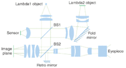
For basic electro-optical systems with few components, optical alignment methods are usually simple. But when systems become more complex it can be difficult to decide where to start and which methods to use (see www.laserfocusworld.com/articles/327817). For example, multiple paths with folds, numerous sources at different wavelengths, off-axis elements, tight tolerances, or tricky components such as lens arrays, cylinders, aspherics, sensors, or digital micromirror devices all can cause alignment issues (see Fig. 1).
But alignment need not be complicated even if the system is complex. In the overwhelming majority of cases, optical alignment methods are a combination of thoughtful mechanics with consideration for adjustment based on feedback from optical instrumentation as necessary. When devising the alignment and assembly processes, a number of general strategies using well-known tools and optical instruments can be useful over a broad range of applications.
Use mechanical constraints
When tolerances are on the order of 25 to 50 µm for centering and a few minutes of arc for tilts, the simple drop-in assembly method that references machined surfaces is one of the most effective and inexpensive alignment techniques, and can be sufficient for most if not all of the system’s alignment. When there are multiple paths and folds in a system, the metal mounts can become very complex. Nonetheless, with modern computerized-numerical-control (CNC) machining, complicated geometries need to be programmed and verified only once and need not be revisited for subsequent parts. By putting the complexity into the metal, the assembly process becomes much simpler; all that is needed is to place the optic in its appropriate location. Shims can be placed symmetrically around the part to take up the majority of any remaining clearance between the optic and its mount to optimize this mechanical approach.
When tolerances are too tight for drop-in assembly, this basic approach is still valuable for getting components close to their optimum position and limiting their deviation from nominal during the alignment process. When mechanical constraints limit the deviation optic’s position from the ideal location, component adjustments are easier and time-consuming gross misalignments are prevented.
Divide and conquer the paths
In systems with folds, beamsplitters, and gratings, the optical paths split and separate. In these cases, each optical path in the system can be divided into segments that are delimited by a splitting or folding element. Here, a strategy should be devised for each segment to ensure that it can be aligned independently without having to iterate through the sequence multiple times.When there are multiple folds that require precise angular alignment, it is often best to align all of the mirrors (or other folding elements) first before inserting any powered elements. Interferometers and autocollimators are well suited to this task, with precise angle gauge blocks and reference prisms providing appropriate reference surfaces. When there are multiple powered elements in a segment, typically it is most convenient to align the lenses in a separate subassembly housing and then mount the completed subassembly into the segment. In systems in which there are multiple paths that share segments, Zygo’s electro-optics group aligns the shared segments first to keep the final adjustments as independent as possible. The team will then select the adjustments to avoid the situation in which satisfying the alignment of one path creates the need to readjust another path that was aligned previously.
Use a surrogate
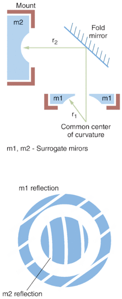
Situations often arise in which it is necessary to measure the tilt or position of a reference such as a mounting surface or an image point, but there is nothing in the optical system that allows for convenient measurement. In these cases, a surrogate part can be designed to be placed in the system temporarily to allow a reference measurement to be made before the next component or subassembly is mounted. Consider a scenario, for example, in which the spacing needs to be measured between a pair of mounts separated by a fold mirror. Direct measurement of the spacing through the fold is difficult to make. However, using an interferometer and a pair of surrogate mirrors of the appropriate radius, the spacing can be measured very accurately. If these surrogates are diamond turned, it is easy to add an additional flat to verify the relative tilt as well. Once the mounting reference surfaces have been verified, the surrogates are removed and the actual components can be mounted (see Fig. 2).
Tooling balls are also useful surrogates for relating optical reference points to mechanical reference points. A high-quality tooling ball, whose center is placed at an object or image point, is a good confocal optical reference point that is easily probed by a coordinate-measuring machine, allowing for high-precision verification that the optical locations are in the correct mechanical positions.
Align active elements last
While not true in every case, active elements, such as an integrated sensor array or display, should be aligned last. This approach is valuable as it allows for a final opportunity to optimize the alignment using performance feedback that is measured through the complete optical system, including the sensor—especially true when multiple imaging paths must be combined and registered to each other. Whenever possible, effort should be made to avoid allowing all six degrees of freedom in the final alignment, as this can greatly complicate the mount and increase material and labor costs. The method used to align the active element may vary greatly depending on the application requirements.
Add secondary features
Many components are difficult or time consuming to align based solely on their fundamental properties. In such cases, our team often adds secondary surfaces or reference features to the part to greatly simplify the alignment. Polarizers with a vendor-applied fiducial mark, diamond-turned aspheres with an integrated flat as a tilt reference, and microlens arrays with secondary alignment features etched into the substrate are some common examples. In each of these cases, the vendor supplies an easy-to-align, nonfunctional reference feature that is precisely registered to the functioning part of the optic to be aligned. Although this approach can add some cost to the component, it can also save much more in assembly labor if done well.
Optical fibers
While an entire article could be devoted to optical-fiber systems, there are some fundamentals worthy of discussion in the current context. First, consideration must be given to management of the fibers. In any mechanical layout, there is a fiber-type-dependent bend-radius limit (based on mechanical stress or optical performance) that must be observed. Second, a provision to handle excess fiber must be included, as it is very difficult to manage fibers to exact lengths. Third, a connector interface needs to be added to the layout using either an external pigtail or internal bulkhead-mounted interface. For the connector interface, optical connectors are designed to be mated to each other and are not nearly as precise as a single component in a mount. Consequently, it is not a good practice to design a fiber interface to a system that relies on a single connector terminated in free space.
Finally, engineers should consider various techniques to couple light into or out of the fiber. For single-mode fibers, active alignment is almost always required involving either the tilting of a fiber collimator subassembly or translation of the fiber tip in x-y-z to maximize coupling. Deformable mounts, where the metal yields under force, are suitable for tilt adjustment for collimator assembly, whereas precision adhesive bonding techniques are typically used in fiber tip alignment. For large-core multimode fibers, pure mechanical alignment may be possible.Tools
Two of the most versatile optical-system alignment tools are the interferometer and autocollimator. Combine either of these tools with an optical flat, and the perpendicularity of any mechanical surface to the optical axis can be easily quantified. Add a set of angle gauge blocks and essentially any angle can be precisely measured. When high precision is required, interferometers have significantly higher sensitivity than a typical alignment collimator. Alternatively, when the precision requirements are not as demanding, an autocollimator may be a better choice as it is much more compact and easier to mount. These tools are not limited to measuring only tilts of flat surfaces. The addition of a transmission sphere to the interferometer or a head lens to the autocollimator allows measurement of the return from a confocal reflection from a spherical optical surface as previously described in the “use a surrogate” section.
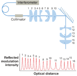
For measuring mechanical displacements, a mechanical height gauge or drop gauge is indispensable. Recently, low-coherence interferometers have become available with a measurement stroke of up to several hundred millimeters. These instruments allow for very precise measurement of spacings of optical elements in situ, including the path through folds (see Fig. 3). Because of the expense of the equipment, this technique is not recommended in the general case, but it can be very powerful in situations in which traditional techniques are not convenient.
For precise alignment of fine optomechanical components such as masks or apertures, a toolmaker’s microscope is a good instrument to use. The stage micrometers and a microscope reticle can make precise measurements of the positions of fiducial marks in x and y, and alignment to a few microns is possible. In addition, a precision retroreflecting cube and a precision penta-prism are useful tools that can aid in assembly.
Paul Townley-Smith is technology development manager in the Optical Systems Division at Zygo, 1590 Corporate Dr., Costa Mesa, CA 92626. Matt Giza is director of sales and marketing in the Optical Systems Division at Zygo, Laurel Brook Rd., Middlefield, CT 06455; e-mail: [email protected]; www.zygo.com.

