MOTION CONTROL: Automated alignment keeps Z machine on target
DAVID E. BLISS and BEDA ESPINOZA
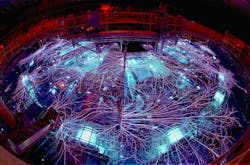
An "earthquake" ripples over a high desert mesa near Albuquerque, NM. The Z machine at Sandia National Laboratories has just fired. For an instant in time, huge electrical currents flow through the pulsed-power machine, generating crushing magnetic fields (see Fig. 1). At its center, a thimble-sized array of thin wires, each one-tenth the diameter of a human hair, vaporizes, implodes on itself, and heats up. Temperatures rise in excess of 2 billion degrees Celsius–hotter than the interior of the sun. X-rays emitted by the extreme plasma compress a small capsule, generating nuclear fusion reactions and releasing neutrons.1 Extreme forces rip apart the center of the machine.
By the next day, the machine's center is rebuilt and new hardware installed for another experiment–a flyer-plate load. This time, the magnetic field will accelerate a solid chunk of material from zero to 92,000 mph in 200 ns, faster than the earth moves around the sun.2 The acceleration is mind-boggling, more than 10 giga g. The impact of the flyer-plate will be used to understand material dynamics during shock compression. A loudspeaker announces "80 kV charge complete. Arming to fire." BOOM, the flyer plate is launched. Ironically, the experiment is long over before the boom is ever heard. Another "earthquake" rattles the buildings.
Z machine
The Z machine is the world's most powerful and most efficient (15%) laboratory x-ray source.3 With its ability to generate high-energy and high-density conditions, Z supports a wide range of science campaigns for the Department of Energy (DOE) and the National Nuclear Security Administration (NNSA) via the measurement of material properties, radiation transport, and complex hydrodynamics. Experiments at Z in support of Inertial Confinement Fusion (ICF) assess target design and x-ray shielding concepts, and validate computer models.
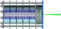
The Z machine functions as a current source, uniquely able to deliver 26 MA to a load. Magnetic fields, which do the work at the load, can exceed 100 MGauss. Z is based on pulsed power technology–a series of capacitors, switches, and transmission lines is configured in a module to compress electrical energy in both space and time (see Fig. 2). The high currents are achieved by connecting in parallel 36 of these nearly identical pulsed power modules. Sitting in a tank 108 ft in diameter and 20 ft deep, the Z machine occupies the volume of two Olympic-size swimming pools.Laser trigger
The laser trigger system (LTS) is based on 36 lasers, one for each module.4 Ultraviolet (UV) light is required to efficiently break down the SF6 (sulfur hexafluoride) gas and create a laser spark. Commercially available frequency-quadrupled, Q-switched, short-cavity Nd:YAG lasers are used. The UV laser pulse is 30 mJ and 4 ns wide. Rapid build-up times in the short cavity result in measured rms jitter of less than 0.2 ns.
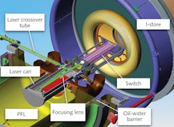
The gas switches and associated energy storage capacitors are submerged in a tank containing about 600,000 gallons of insulating transformer oil while the pulse-forming components sit in a similar volume of deionized water. The laser beam must be delivered through an oil-tight beamline. The lasers are mounted in the basement of Z on nine vertical Newport optical tables. Each table delivers four laser beams through the tank floor into an oil-tight tower. Each vertical optical table is mounted on a floating concrete pile that isolates it from much of the seismic shock coupled into the building. Above the lasers, the metal floor of the oil tank shields the electronics from the EMP produced by Z. From inside the tower in the oil tank, the laser beam must be transported across 5 MV to the inner conductor and gas switch. Teflon tubes pressurized with SF6 are used to cross over the high-voltage region (see Fig. 4).System alignment
Six mirrors steer the laser beam around pulsed power components and into the switch. Reflective targets are placed on or behind the various optics along the optical path to aid with beam alignment (see Fig. 5). Targets with different shapes identify the specific optic. Green second-harmonic light leaking from the laser illuminates the reflective targets and is imaged by an inexpensive CCD camera. Double stack mirrors control the reflectivity of the green light while reflecting all of the UV light. Mirrors that are partially reflective in the green are used in front of targets, allowing some green through to the target. A partially reflective turning mirror is also used in front of the alignment camera, allowing it to look down the optical axis of the system. A 532 nm notch filter ensures that the CCD camera is sensitive only to the green laser light. Two key benefits of using green leakage light are that no UV light need be sacrificed for alignment images (allowing all the UV energy to be used to trigger the switch), and that chromatic aberrations in the beam expander cause the green beam to diverge and flood-illuminate the targets.Flood illumination is important because when seismic shock causes the pulsed power components to shift and the LTS is misaligned, a larger beam is easier to find for realignment of the targets. Also, a wider beam provides more real estate to place targets around the outside of the mirrors. This simplifies analyzing alignment images that would quickly become crowded and confusing if all the targets were located behind mirrors. Aberrations are not always the enemy in an optical design but can be used to an advantage if one is clever or lucky or both.
Software written in LabView controls the LTS alignment by acquiring video images, controlling laser output, reading photodiode times, and positioning the 30 nm resolution New Focus Picomotor mirror mounts. These mounts have proven to be stable and hold position even through the "earthquakes." An optical-fiber-based light collection system evaluates how bright the laser spark is in the switch under oil. Alignment of all 36 lasers in the switches takes the LTS operator about 10 minutes facilitating an aggressive experimental schedule.
This laser trigger system for the Z machine has been built from commercial off the shelf (COTS) components. The Nd:YAG lasers have proven durable, easily swapped out for maintenance. Fast realignment of the optical path is made possible with the remotely controlled adjustable mirror mounts. The modular design has improved performance while minimizing maintenance downtime. In the ongoing quest for fusion energy with large experimental facilities like Z and NIF, stable and smoothly functioning subsystems enable scientists to focus on experiments without being distracted by facility operations.
REFERENCES
- M.G. Haines et al., "Ion Viscous Heating in a Magnetohydrodynamically Unstable Z Pinch at Over 2x10⁹ Kelvin," Phys. Rev. Lett. 96, 075003 (2006).
- M.D. Knudson, M.P. Desjarlais, "Shock Compression of Quartz to 1.6 TPa: Redefining a Pressure Standard," Phys. Rev. Lett. 103, 225501 (2009).
- M.K. Matzen, "Z pinches as intense x-ray sources for high-energy density physics applications," Phys. Plasmas 4, 1519 (1997).
- D.E. Bliss et al., "A new laser trigger system for current pulse shaping and jitter reduction on Z," 14th IEEE International Pulsed Power Conference, June 15–18, 2003, Dallas, TX, USA; Vol.1, p.179–82.
For further information see www.sandia.gov/pulsedpower/facilities/index.html.
David E. Bliss is a staff scientist at Sandia Nation Laboratories, Z-Backlighter Laser Facility, Albuquerque, NM, and Beda Espinoza is senior manager, product marketing–motion at Newport Corp. in Irvine, CA; e-mail [email protected]; www.newport.com.


