SCOTT SPARROLD and GEOFFREY FORMAN
Advances in fields such as machine vision and photonics continuously drive change in optical element design by increasing the need for both higher-performing optical components and more compact systems. Hybrid optical components capable of replacing a multielement design are now emerging to satisfy customer demands by delivering superior performance while minimizing system size.
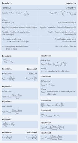
A hybrid optical component is so named because it has both refractive and diffractive surfaces for manipulating light. The power of a hybrid optical component is defined by the interaction of light from the two surfaces, and can be calculated by adding together the individual powers of the two surfaces. Equations 1a and 1b provide the respective refractive and diffractive powers1-3 of a hybrid lens at a given wavelength.
The phase front power coefficient of the diffractive surface (C2) is specified in units of radians and can have terms—including higher-order spherical aberrations—that affect more than power. When using ray-trace simulation software for designing hybrids, it is important to refer to the user manual. Some codes specify phase in system units rather than radians.
Manufacturing hybrid optics
Manufacture of hybrid optics typically uses one of two techniques: diamond turning or injection molding. Diamond turning, which involves mechanically shaping a lens with diamond-tipped tools, is ideal for recurring, single-component production. However, because of the mechanical process and the time needed to create an individual lens, diamond turning is expensive for mass production and can be difficult or impossible to use with lenses having 10 mm diameter or less.
Injection molding—the filling of a mold with molten plastic to form a lens—is ideal for large-volume production. Although less expensive for volume production than diamond turning, injection molding requires special care because plastic lacks the thermal stability of glass. Failure to properly cool the lens after molding may result in shrinkage and buildup of additional physical stresses, both of which may interfere with the lens’ optical properties. For the infrared (IR) spectrum, chalcogenide glasses are molded to produce a hybrid.
Advantages of hybrid optics
In addition to simplifying system size by reducing element count, hybrid optical components have several other advantages when compared to traditional optics. For one, single hybrids can be made to reduce or eliminate chromatic aberration, which occurs in conventional lenses when different wavelengths of light focus at different points along the optical axis. Left uncorrected, chromatic aberration manifests itself as colored fringes along the image.
Color correction is best defined by understanding color correction theory. In a hybrid, the diffractive and refractive surfaces act as individual optical components. To eliminate chromatic aberration, a color-corrected optic corrects for dispersion—the term used to define how focal length changes with wavelength. Equation 2 defines the change in power versus wavelength for a lens due to dispersion.1,4
The subscripts S, M, and L denote the short, middle, and long wavelengths. V is the inverse of dispersion. For visible wavelengths, V is referred to as the Abbe number. For nonvisible wavelengths, V is referred to as the V number.
The conventional color-corrected lens–the achromat—is constructed by balancing the optical power and dispersion of two refractive lenses to make the short and long wavelengths come to a common focus. But while refractive dispersion is a positive value, diffractive dispersion is negative, as seen in Equations 3a and 3b.
Hybrids, then, can achieve color correction within a single lens by balancing the optical power and dispersion of its refractive and diffractive surfaces. Equations 4a and 4b can be used to calculate the power of the refractive and diffractive surfaces.
However, this correction only works at the two wavelength extremes due to dispersion nonlinearity. Partial dispersion, the measure of dispersion nonlinearity, is thus a critical factor to consider because it is used to calculate a doublet’s secondary color: the defocus of the middle wavelength relative to the extreme wavelengths. Secondary color can be calculated using Equation 5, where Δ is used to denote the change from refractive to diffractive.
Most refractive materials fall upon the glass line, and most glasses have a similar P/V value. In the visible, this value is approximately 0.005. To reduce the secondary color, the partials between the two elements must be closely matched, such as using silicon and germanium (Ge) in a color-corrected doublet in the 3–5 µm wavelength range. Partial dispersion can be calculated using Equations 6a and 6b.
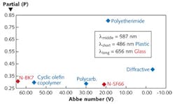
When designing an imaging system with multiple refractive elements, the selection of starting component types uses a partial glass map similar to Fig. 1, which is an example of a map for visible-wavelength plastics5-7, several glasses, and diffractives. When designing a hybrid optic, it is important to place the diffractive on the glass chart. For a two-element design, the partials must be closely matched.
If two elements do not have matched partials, then three materials are selected so that the area of the triangle formed by the three components on the partial chart is as large as possible. For instance, the diffractive–polyethermide–N-BK7 would be a maximized triangle; the two components approximate a partial that matches the third component.
Another advantage to hybrid optics is that they can be designed to be less sensitive to thermal changes. Equations 7a and 7b can be used to determine the thermal optic coefficient, which is needed to calculate the thermal defocus, or the change in lens focus versus temperature. If changes in wavelength are replaced with changes in temperature, the focal length solutions will remain the same—also known as thermal dispersion.
The thermal optic coefficients are only approximations, as the change in refraction due to the change in air temperature is not considered.
Equation 8a can be used to predict the thermal defocus of a lens by itself, while Equation 8b includes housing or mounting effects.
To make the two surfaces insensitive to thermal changes, the coefficient of expansion of the housing (αhousing) must be included in the calculation, as shown in Equations 9a and 9b.
Disadvantages of hybrid optics
There are several disadvantages associated with hybrid optics. Although similar to aspheres in price, hybrid optical components are typically more expensive than standard optics because of the recurring added cost for diamond turning, or a tooling cost for injection molding.
Another disadvantage is that when used with a broadband light source, a hybrid’s diffraction efficiency varies at different wavelengths. For example, for a visible system with the center wavelength selected at 587 nm, the efficiency of a hybrid at 656 nm is 96.4%, while the efficiency at 486 nm drops to 86.6%. Fortunately, this issue is not present with lasers or other monochromatic sources.
Finally, hybrid optic designs may be unsuitable for use at shorter wavelengths. Short wavelengths are often below the linear tolerances of the hybrid optical design, potentially causing drastic decreases in performance of the lens.
Hybrid optic applications
Depending on the component, hybrid optics are ideal for a range of applications.
Axial imaging lens: Comparing glass doublets versus a plastic hybrid—For example, hybrid aspheric lenses combine the color correction performance of a hybrid with an asphere’s ability to eliminate spherical aberration, ideal for imaging and ophthalmic applications, and for use with laser and broadband illumination sources.
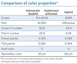
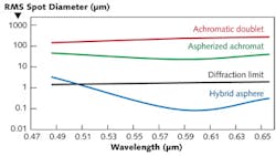
For example, Fig. 2 shows a spot size comparison of a 25 mm diameter, f/1.2 plastic hybrid asphere, achromatic doublet, and aspherized achromat. The hybrid demonstrates the smallest spot size over the entire wavelength range. Color properties are provided in the table.Hybrid acylinder lenses are designed to provide color correction while creating thin line profiles. For performance in the IR, Ge hybrid aspheric lenses are ideal for imaging, broadband midwave-IR applications, and for integration into Fourier transform IR spectrometers.
Imaging application: Double Gauss—The double Gauss lens design is the basis for modern camera lenses. Its design contains a singlet and doublet pair that symmetrically surround an iris (aperture stop). The symmetry allows for balancing of field aberrations and for a fast f-number with a considerable field of view. Prior studies9 have shown that its performance can be increased by aspherizing the last element near the image plane—also an ideal location for a hybrid element. For example, the optical performance (f/2.1, 42° field of view) in terms of modulation transfer function (MTF) at a spatial frequency of 15 lp/mm for a spherical design is 32% full-field, 44% axial. For an asphere aft element, the performance is 36% full-field, 75% axial, and a hybrid provides 41% and 79%, respectively.
While a hybrid provides only a small increase to MTF when compared to an asphere, it shows a dramatic reduction in axial color: 32 µm versus 124 µm. This reduction in axial color will allow the elimination of additional optical lenses without compromising optical performance.
Axial imaging lens for removing thermal defocus—A hybrid optic’s insensitivity to temperature change is ideal for laser applications. Comparing a refractive asphere and a hybrid—both f/5 with a 100 mm focal length—using a frequency-doubled Nd:YAG laser at 530 nm over a temperature range of -40° to 80°C shows the difference. Using a cyclic olefin copolymer from Zeon Chemicals—E48R—which has a coefficient of thermal expansion of 60*10-6 and a dn/dT of -100*10-6, the hybrid component is not affected by the change in temperature. However, each element of the asphere suffers a degree of defocus in the aluminum housing (α = 23.6*10-6), ranging from ±860 µm for an N-BK7 asphere to ±1.6 mm for a plastic asphere. For reference, the quarter-wave depth of focus is roughly ±0.025 mm.Improvements in hybrid optical component design will continue in response to customer demand. As machine and molding tolerances increase in accuracy, for instance, hybrid optics will increase in efficiency and show improving performance when used with ultraviolet and other short-wavelength light. The compact size, color correction, and thermal stability ensure that applications for hybrid optics will remain on the rise.
ACKNOWLEDGMENT
Special acknowledgment to Dr. Michael Schaub, Raytheon Missile Systems, for supplying sample lens prescriptions and reference material.
REFERENCES
1. J.E. Greivenkamp, Field Guide to Geometrical Optics, SPIE (December 2003).
2. M. Riedl, “Diamond Turned diffractive optical elements for the infrared,” Proc. SPIE, 2540, 257 (1995); doi:10.1117/12.219529.
3. D. O’Shea, T. Suleski, A. Kathman, and D. Prather, Diffractive Optics: Design, Fabrication, and Test, SPIE (December 2003).
4. S. Sparrold, Optics Realm web site, “Color Correction”; http://bit.ly/rCtg1c.
5. P.R. Tolley, “Pushing the Polymer Envelope,” Syntec Optics white paper, orig. presented at SPIE Optics + Photonics (2005); http://bit.ly/vCr6zO.
6. S. Baumer, Handbook of Plastic Optics, 2nd Edition, Wiley-VCH (April 2010).
7. M. Schaub, J Schwiegerling, E Fest, A. Symmons, and R. Shepard, Molded Optics: Design and Manufacture, CRC Press (April 2011).
8. G. Behrmann and J. Bowen, “The influence of Temperature on Diffractive Lens Performance,” Appl. Opt., 32, 14, 2483–2489 (1993).
9. S. Sparrold “Placement of Aspheres in an Optical System to Increase Optical Performance,” NASA Tech Briefs, 34, 4, 48–52 (April 2010); http://bit.ly/rOil43.
Scott Sparrold is a senior optical engineer and Geoffrey Forman is a product marketing specialist with Edmund Optics, 101 East Gloucester Pike, Barrington, NJ 08007; e-mail: [email protected]; www.edmundoptics.com.
