“Slow light” devices, which slow and control the group velocity of light in a medium by some means, come in many forms. These range from the straightforward (dispersive optical fiber) to the extremely complex (temperature-controlled atomic vapors). While the latter can have large effects, it usually requires a large and fragile setup and is normally reserved for the laboratory. In contrast, the former, while producing small effects, is rugged and simple enough for use in the field.
A team of researchers from the University of Rochester (Rochester, NY) and the University of Ottawa (Ottawa, ON, Canada) is using a combination of standard singlemode fiber and highly dispersive fiber to create a tunable slow-light effect that is the basis of a phased-array beam steerer for a light detection and ranging (lidar) system.1 Termed slow-light detection and ranging (slidar), the approach contains a slow-light tunable delay element in each of the three channels of the phased array. The three delays are tuned relative to each other by changing the wavelength of the tunable laser-diode source.
A simple phased array
The traditional way to steer a lidar beam is to mount its optics on a gimbal. The high rotational inertia of this type of setup has led to the development of phased-array lidar, where a row of individual emitting channels has a linear delay across the elements that can be varied to steer the optical beam. Various approaches to phase delay have included the use of electro-optic modulators and liquid-crystal phase-control elements.
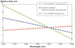
The Rochester-Ottawa approach is different, and simpler as well. Three different sections of fiber serve as the three variable-delay channels: a 1.1 km length of standard singlemode fiber (SMF), a 0.55 km section of SMF spliced to a 0.55 km section of dispersion-compensating fiber (DCF), and a 1.1 km length of DCF. These fibers and their lengths are chosen such that their relative delay is zero at a chosen wavelength (for example, 1550 nm), as their refractive index is the same at that wavelength. Due to the fibers’ different dispersions, their refractive indices all change at different rates (although all approximately linearly) as a function of wavelength over the 1530–1560 nm region (see Fig. 1). As a result, the phase variation across the three-channel phased array is a linear function of wavelength.
In the optical setup, an optical reference channel is first split off from the laser output and shifted in frequency by 55 MHz by an acousto-optic modulator; the rest of the signal is “carved” into 1–4 ns pulses by an intensity-modulating electro-optic modulator (EOM), then split into three and fed into the sections of variable-delay optical fiber. Each channel also includes a phase-modulating EOM for phase control and an erbium-doped fiber amplifier (EDFA) to increase the output.
The researchers would like to ultimately create a slidar with a 1 m aperture and a range of at least 1 km; however, their first prototype is considerably smaller and fits within a laboratory. After collimation, the three channels each have 2.1-mm-diameter apertures, forming a full effective aperture of 6.6 mm, and the target is placed 6 m away, resulting in a distance/aperture ratio similar to that of the proposed full-scale system. To control the phases of the channels, each of the three channels is independently phase-locked to the 55-MHz-shifted reference channel and the beat signals processed to produce an error signal to ensure that the phase-modulating EOM locks the phase to the reference signal.
Testing shows high accuracy
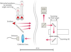
To test the phased array’s effectiveness, two of the three output collimators are put on translation stages and moved to create the proper phase delays; the system is then phaselocked and wavelength-tuned to cancel out the mechanically induced phase delays (see Fig. 2). Six meters away, the far-field light is divided by a beamsplitter, with part going to a CCD camera that images the far-field pattern, and the other entering a retroreflective scanning element containing a 0.44 mm slit, with the retroreflected light collected by a 3 GHz photodetector back near the source. (The target is a retroreflector rather than a scatterer due to the low-energy pulses produced by the first prototype, say the researchers.)A carved pulse is first imaged without phaselocking, producing what looks like a low-intensity fringe pattern but what is really a higher-intensity fringe pattern that is shifting rapidly around. When phaselocking is initiated, the fringes sharpen and the intensity of the return pulse stabilizes, as hoped for. Next, a linear phase delay across the aperture is mechanically induced, imitating an angular beam shift of 20°, shifting the fringe pattern and lowering the intensity of the return beam. Finally, the system is wavelength-tuned to bring the beam back to 0°, which is achieved by changing the wavelength from 1550 to 1542 nm. The 8 nm wavelength change corresponds to a relative pulse-delay adjustment of 1.14 ns.
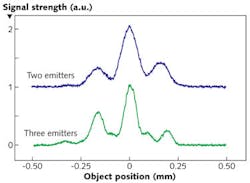
In addition, the range-measurement accuracy is determined by measuring the return time of the emitted pulses while translating the retroreflective scanning element in 1 cm steps. The fitted data show a second-order moment of 0.38 mm. The lateral measurement accuracy should improve as the number of emitters (of the same size) is increased: Indeed, the central lobe of the far-field pattern narrows when three emitters are used instead of two (see Fig. 3).The design easily accommodates more than three emitters. The researchers say that a nonuniform spacing of emitters across the aperture could help to reduce the size of the fringe pattern’s side lobes. A full-scale system would also need to emit higher-energy pulses; this would be achieved by using more-powerful EDFAs. The concept could be extended to scanning in two dimensions by creating a 2D array of emitters, the researchers add.
REFERENCE
1. A.Schweinsberg et al., Opt. Exp., 19, 17, 15760 (Aug. 15, 2011).

John Wallace | Senior Technical Editor (1998-2022)
John Wallace was with Laser Focus World for nearly 25 years, retiring in late June 2022. He obtained a bachelor's degree in mechanical engineering and physics at Rutgers University and a master's in optical engineering at the University of Rochester. Before becoming an editor, John worked as an engineer at RCA, Exxon, Eastman Kodak, and GCA Corporation.

