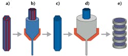
A stack-and-draw process for fabricating nanostructured micro-optics developed by engineers at Heriot-Watt University (Edinburgh, Scotland) and the Institute of Electronic Materials Technology (Warsaw, Poland) is pointing the way to low-cost manufacture of microlenses and other small optical elements.1 In addition, it allows the making of novel broadband birefringent micro-optics.
In the process, many glass rods of a certain diameter between 0.25 and 1 mm are assembled by hand into a fiber preform that may contain between 2000 and 10,000 individual rods (see figure). The preform, on the order of 50 mm in diameter, contains rods of one type of glass in a matrix of a second type of glass. The preform is then drawn down to a 1 mm diameter; these intermediate preforms are then arrayed together to an approximately 50 mm diameter and drawn down again to a 1 mm final diameter or smaller.
The result is a nanostructured glass with a refractive index intermediate between the two starting glasses. By varying the ratio of the rods in the preform, the index can be custom-tailored. And, by assembling intermediate preforms together that have different refractive indices, the result is a microlens with areas of differing index—for example, a Fresnel-type microlens with rings that each have their own distinct indices.
The two glasses must have matching mechanical and thermal properties so that there are not discontinuities when the preforms are drawn. The experimenters used F2, an off-the-shelf glass by Schott (Mainz, Germany), and a custom glass termed NC21A developed at the Institute of Electronic Materials.
The final nanostructure is far enough below a wavelength in period that no diffraction occurs in the rod lattice; instead, an effective refractive index is the result, with the index being a spatial average of the refractive indices of the component nanorods. To confirm this theoretically, the researchers compared their effective-refractive-index calculations with a fully vectorial solution to Maxwell’s curl equations and found the difference was small.
An example fabricated microlens contains seven different kinds of “metarod” (the structures corresponding to the intermediate preforms); each metarod is 1.2 μm in diameter and contains 2500 rods within it of 20 nm diameter. About 10,000 of these metarods are hexagonally packed in a Fresnel-zone pattern to form the lens. Fabricating the lenses is easy: Just take a lateral slice from the final drawn fiber and polish the faces flat. Diffraction-limited performance was achieved at 633 nm (0.6 μm spot size) and 850 nm (0.9 μm spot size).
Form birefringence
A different type of nanostructure can be created that has form birefringence—which could be taken advantage of in some situations. If the initial structure to be drawn down consists of glass slabs with alternating refractive indices, after drawing the result is a nanostructured birefringent material. The glass slabs were created by patterning the initial 1-mm-diameter glass rods in alternating linear arrays before drawing down. In this case, the structure did not have to be reduced in size as much; the quarter- to half-wavelength period meant an easier draw-down procedure.
The researchers calculated the birefringence over a wavelength range from 500 to 2000 nm (the birefringence varies with wavelength as a result of dispersion) as a function of the nanostructure period; this allowed them to choose the best experimental period for a fabricated nanostructure. The birefringence of the fabricated structure was characterized, showing that the 10.77-mm-thick sample had a retardation (the phase difference at exit between the two orthogonal polarizations) between 5.3 and 5.7 radians.
The researchers note that the flexibility in positioning rods of different glass types, and arranging the metarods, could allow the fabrication of very interesting optics that include nonspheric index profiles and general diffractive optical structures.
ACKNOWLEDGMENT
Laser Focus World has a partnership with Advanced Optical Technologies to bring readers coverage of the journal’s content.
REFERENCE
1. M.R. Taghizadeh et al., Adv. Opt. Technol., 1, 3 (2012).

John Wallace | Senior Technical Editor (1998-2022)
John Wallace was with Laser Focus World for nearly 25 years, retiring in late June 2022. He obtained a bachelor's degree in mechanical engineering and physics at Rutgers University and a master's in optical engineering at the University of Rochester. Before becoming an editor, John worked as an engineer at RCA, Exxon, Eastman Kodak, and GCA Corporation.
