PHOTONICS APPLIED: MATERIALS PROCESSING: Successful laser welding demands optimized laser joint design

As the use of lasers in industrial materials processing applications becomes more widespread, designers and product engineers need to gain familiarity not only with the properties, advantages, and applicability of the laser welding process but also with how to design components and assemblies for successful laser welding. While the choice of laser type, component material selection, component part preparation, and part fixturing are all critical to successful implementation of the laser-welding process, all these points are moot without a well-designed, laser-weldable joint.
Before jumping into designing for laser welding, it is important to understand the compelling reasons why laser joining has been implemented by literally thousands of manufacturers on almost every continent today for thousands of products—from extremely small components to very large structures. Laser joining often has higher throughput and improved performance compared to traditional welding techniques due to several factors: remote welding and multiplexing/beam-sharing; minimized workpiece distortion due to the small heat-affected zone; increased component strength and/or reduction of component size and weight due to higher-strength welds; noncontact, single-sided access for welding in difficult-to-reach areas; minimal production downtime due to redundancy and ease of backup; and cost savings due to reduced material weight and scrap as well as reduced floor-space requirements. Although these benefits have been discussed over the years, the ultimate way to capitalize on the laser-welding process is to design components and assemblies for optimum joining with light.
Design-for-manufacturing principles
Compared to traditional resistance spot welding and arc welding, laser welding will continue to offer fabrication solutions across a variety of industries including automotive, appliance, agricultural, marine, aerospace, medical, food and beverage, and more. The primary considerations in minimizing production cost and maximizing part throughput for laser-welding processes is, when possible, to optimize the physical configuration and parameters or modify the assembly processes for the material components to be welded.
Material optimization
Key design-for-manufacturing methods to improve the laser joining process include flange-width modification, gage-thickness reduction, and use of alternate materials and structures.
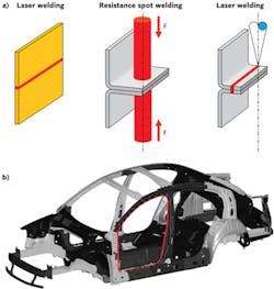
Because laser welding is a single-sided process with narrow-beam access, flange widths can be reduced or eliminated, in turn reducing material component weight and cost (see Fig. 1). A flange for a resistance spot weld can be upwards of 20 mm, whereas for laser welding, the flange can be reduced to less than 10 mm or even eliminated if the flange with an overlap weld is replaced by a simple seam design with a butt weld. Depending upon how much resistance spot welding a particular product has, the potential for material cost and weight savings can be enormous.
Component weight and cost are also minimized by reducing material gage thickness, which can actually increase component strength through optimized weld shapes or continuous weld seams in high-stress regions where parts are normally spot-welded. In an auto body side-door, for example, laser stitches or short seams can join components across the upper roof frame and lower rocker panel. A continuous laser seam—impossible to create with a resistance spot-welding gun—can eliminate the need for additional reinforcements in the areas where strength is critical for passenger safety. These long seams as well as "C" and "S" shaped laser welds and parallel welds are all tools in the engineer's laser-welding portfolio that can meet the loading and stresses of the materials-processing task at hand.
Whenever sheet metal is attached to structural tubing using resistance spot welding, access holes are required to allow ingress of the lower electrode. With laser welding's single-sided accessibility, these access holes can be eliminated and enable thinner-walled tubes or smaller sectioned tubes; either way, component weight and cost is again reduced. With single-sided laser access, the designer is also free to design, package, and assemble the product knowing that access from only one side is required-a rather freeing paradigm compared to some conventional joining techniques.
Preprocess and assembly modifications
In addition to the use of optimized or alternate material components for laser joining applications, manufacturing and preprocess assembly steps can be modified to gain further manufacturing cost savings.
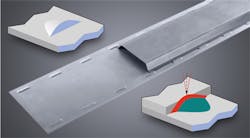
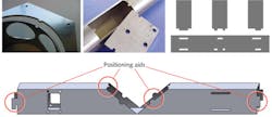
These features act simultaneously as part locators and weld-seam locations. For example, TRUMPF has a self-positioning design feature called a K-joint that can be used anywhere sheet metal or profiles are joined with flanges or lap joints by means of resistance spot welding (see Fig. 2). Parts preparation for the K-joint involves stamping small depressions at intervals along a joint contour. These features act simultaneously as part locators and weld-seam locations. Since the K-joint transforms what would have been an overlap weld to a butt weld, zinc-coated steels can be welded without issue. The K-joint can also be welded from both sides, providing increased manufacturing flexibility.The right tool for the right job
Even if you follow all the aforementioned guidelines and design a component part ideal for laser welding, it is imperative that the fit-up of the components to be joined is appropriate for the laser-welding process. The general rule regarding fit-up gap is that a gap of 10% of the thickness of the thinnest component in butt welding or 10% of the thickness of the top component in overlap welding can be accommodated by laser welding. However, this is a general rule only and a number of factors can affect the amount of gap that can be bridged in laser-welding applications.
When designing for laser welding, manufacturing engineers need to ensure that the wavelength, spot size, power distribution within the focus spot, and the depth of focus of the laser are not just appropriate but are best for the application in question. This will ensure that the process window within the production environment is as large as possible—an unquestionable key to success.
When laser welding in an overlap configuration, the strength of the joint comes from the weld-fusion area at the interface of the two components. In this case, a relatively large spot size and top-hat distribution will provide a relatively large weld width at the interface compared with a smaller spot and Gaussian distribution. In butt-joint cases where edge geometries are poor, fit-up is bad, or seam position is slightly unpredictable, larger focused spot sizes offer more forgiveness and a greater process window. On the other hand, welding dimensionally critical, precision press-fit components (such as those in an automobile powertrain) benefits from a smaller focused spot size with narrow welds and low distortion.
Another consideration is spatter. When welding with high-power disk and fiber lasers, more expulsion (spatter) is generated compared to the carbon-dioxide (CO2) laser. While the reason is complicated and debatable, it is related to wavelength and keyhole geometry (incidence angle) and how these parameters influence energy absorption.
The difference in the amount of spatter can be significant or insignificant, depending on the product being welded, weld depth, and weld speed. In general, the deeper the weld penetration (very slow speed of <2 m/min) and the faster the weld speed (greater than about 6 m/min), the greater the amount of weld spatter. One application where minimizing the spatter is crucial is laser welding of stainless-steel tubes. Whether used in the food industry or for automotive exhaust pipes, these tubes cannot have spatter on the inside of the tube due to function, nor on the outside of the tube due to form. Here, the CO2 laser excels.Another spatter-critical application is welding of powertrain components. The problem herein lies in combining really hard small particles with high-speed rotating gears and again, the CO2 laser has the advantage. Fortunately, there are numerous welding applications where spatter generation is inconsequential.
While it is tempting to take a maximum gap value for an assembly that's been designed for another joining technique and try to force-fit laser welding, design engineers should instead attempt to design or redesign components to reduce costs, improve productivity, and essentially optimize the manufacturing process. The two keys to success for any laser-welding application are selecting the right tool for the job and following available design-for-manufacturing guidelines.
David Havrilla | Manager of Products and Applications, TRUMPF Laser Technology Center
David Havrilla is the manager of products and applications at the TRUMPF Laser Technology Center (Plymouth, MI).


