OPTICAL RESONATORS: Optomechanical accelerometer acts fast
An optical accelerometer developed by engineers at the California Institute of Technology (Caltech; Pasadena, CA) is potentially smaller, more sensitive, and more versatile than the electrical accelerometers commonly found in cell phones. In addition to use in consumer devices, the accelerometer could find use in aircraft, oil and gas exploration, and biomedical applications. The sensor is sensitive to motions that occur in tens of microseconds.
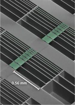
The accelerometer’s optical cavity is only about 20 μm long, 1 μm wide, and a few tenths of a micron thick. It consists of two nanoscale silicon nitride mechanical beams, situated like the two sides of a zipper, with one side attached to a proof mass (which serves as the inertial reference); each beam has a 1D array of holes that forms a photonic crystal.
When laser light enters the system, the nanobeams act like light pipes, bringing the light into an area where it bounces back and forth between the holes in the nanobeams. When the tethered proof mass moves, it changes the relative positions of the two nanobeams, resulting in a change in the direction of the laser light leaving the system. The reflected laser signal is in fact tremendously sensitive to the motion of the proof mass, with displacements as small as a few femtometers being probed on the time scale of a second.
In an example device, the mass resonates at 27.5 kHz and has a mechanical Q factor of 1.4 × 10⁶ in vacuum. The optical cavity is designed to operate at 1537 nm and has an optical Q factor of 9500 at that wavelength. The laser source has a linewidth below 300 kHz and is tuned to the “red” side of the cavity resonance, creating fluctuations in beam position as a function of beam separation, which are measured with a position-sensitive detector (PSD). The readout of mechanical motion is shot-noise-limited, resulting in a precision near the standard quantum limit.
The device was calibrated by mounting it on a shake table driven by a piezoactuator. Two commercial accelerometers were also mounted to the table for calibration purposes. The thermally limited acceleration resolution was estimated to be 2.0 μg Hz-1/2, close to the theoretical value of 1.4 μg Hz-1/2. The linear dynamic range of the device at a drive frequency of 10 kHz was measured to be at least 40 dB.
Optical cooling
Because the cavity and proof mass are so small, the light resonating in the system pushes the proof mass so that when the proof mass moves one way, the light helps push it further; conversely, when the proof mass moves the other way, the light pulls it in. As a result, the laser light dampens the proof mass’s motion.
“Most sensors are completely limited by thermal noise, or mechanical vibrations—they jiggle around at room temperature, and applied accelerations get lost in that noise,” says Oskar Painter, the team leader. “In our device, the light applies a force that tends to reduce the thermal motion, cooling the system.” This cooling—down to a temperature of 3 K in the current devices—increases the range of accelerations that the device can measure, making it capable of measuring both extremely small and extremely large accelerations.
The team envisions its optical accelerometers becoming integrated with lasers and detectors in silicon microchips. Painter notes that a lot of engineering work still needs to be done to make this happen.
REFERENCE
1. A.G. Krause et al., Nat. Photon.; doi:10.1038/NPHOTON.2012.245 (2012).

John Wallace | Senior Technical Editor (1998-2022)
John Wallace was with Laser Focus World for nearly 25 years, retiring in late June 2022. He obtained a bachelor's degree in mechanical engineering and physics at Rutgers University and a master's in optical engineering at the University of Rochester. Before becoming an editor, John worked as an engineer at RCA, Exxon, Eastman Kodak, and GCA Corporation.
