DESIGN FOR MANUFACTURING: Practical design software eases asphere manufacturability
Designing aspheric surfaces is far easier than making or testing them, but manufacturing and testing considerations can be (and usually are, whether the designer knows it or not) made in the design stage. Early collaboration with the lens fabricator is vital to get the best performance at the lowest price with the least part-to-part variability.
Fortunately, recent design tool and optical software advances make it much easier to design economical, manufacturable, and testable aspheric surfaces. Using the manufacturing methods of Optimax and ZEMAX optical system design software, it is possible to map manufacturing needs into the design process as early as possible.
Locking-in lens specifications
Lens designs begin with some basic specifications—f-number (f/#), focal length, and aperture, for example—that are then used to build an initial design.1 After clear aperture is defined for each surface, center thicknesses are assigned for each lens element, establishing both aspect ratio (diameter/center thickness) and edge thickness for the lens.
After evaluating the system, the designer may choose certain surfaces to become aspheric, choosing both the number of surfaces and the global shape of the surface to be aspherized.2 For each asphere, the designer chooses a conic term and the maximum exponential order of the aspheric terms. The combination of these choices defines the aspheric departure, local curvature, and number of inflection points. These lens specifications (clear aperture, aspect ratio, edge thickness, global shape, aspheric departure, local curvature, inflection points) are established early in the design, and also happen to have the most influence on the asphere manufacturing and measurement process.
Consequences for the lens fabricator
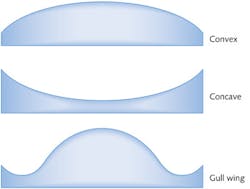
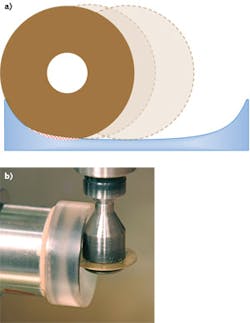
The lens fabricator chooses a fabrication process by first looking at the asphere's global shape: convex, concave, or gull-wing shaped (see Fig. 1). These global shape descriptors are listed in order of increasing complexity and cost, and each has unique challenges. Globally convex aspheres typically offer fewer limitations in manufacturing, but interferometric measurement has more limitations. The opposite is true for globally concave surfaces, with more challenges in manufacturing—specifically regarding tool radius and tool clearance—than in measurement (see Fig. 2). Gull-wing aspheres, sharing characteristics of both convex and concave aspheres, have challenges in both manufacture and measurement.Tool radius is defined by the local radius of curvature of the aspheric surface, and tool radius can never be larger than the shortest local radius to be created. To overcome this issue, the lens fabricator can use shorter-radius tools, but solving tool radius issues often creates tool clearance issues, especially for higher-numerical-aperture lens systems. Local radius of curvature has more influence than maximum tool radius. If the local radius changes too quickly, the fringe density in an interferometric measurement may be unmanageable.
In addition, gull-wing aspheres contain inflection points, and these are challenging to current stitching interferometry. Interferometric testing capability is less possible once an inflection point occurs inside the clear aperture, limiting the lens fabricator to profilometry—which limits how low form error can be held and hinders detection and correction of nonaxisymmetric form errors.
Complexity is also controlled through restraint in adding aspheric coefficients.3 Adding aspheric coefficients adds complexity and with it, cost, creating a point of diminishing returns as coefficient terms are added.4 Fourth-order terms fix fourth-order errors, meaning a sixth-order term adds nothing to a fourth-order correcting asphere except cost.
Aspect ratio also comes into play when determining just how low form error can be held. Parts flex and move during polishing, and this flexing gets more pronounced as aspect ratio increases. Form error of high-aspect-ratio parts (>12:1) can change enough to move the part out of tolerance when no longer held in place for polishing.
Aspheric surfaces are polished using subaperture techniques, where the contact area of the polishing tool is significantly smaller (10–100X) than the clear aperture.5 The subaperture polishing tool leaves artifacts when it starts and stops polishing, requiring extra aperture to be available during processing. The lens fabricator leaves the parts oversized in diameter to provide room to enter and exit clear aperture, typically adding 4 mm to allow for tool overrun.
This oversized diameter comes into play in two ways. First, if the aspheric form is well behaved over the clear aperture but radically changes or goes indeterminate in the tool overrun add-on aperture, manufacture or measurement may not be possible. Second, in each manufacturing step the fabricator uses the other lens surface and the diameter to position the aspheric axis. If the edge thickness is too small, the diameter may be useless as a datum or the part may be too fragile to process. For a 25-mm-diameter lens, edge thickness needs to be at least 1 mm after beveling, adding on another 0.25 mm per 25 mm of diameter.
Optical design duties
Given all the consequences for the lens fabricator of the designer's choices, modern software allows a range of techniques (best performed in the order presented) that help the lens designer ensure that his or her design is as manufacturable as possible.
Use suitable constraints when you start designing your system; that is, always add some extra margin to the computed apertures so there is edge thickness available for mounting and handling (see Fig. 3). This is easily automated, and can be expressed as either or both a margin in distance or percent. Also, putting boundaries on lens, edge, and air-gap thicknesses prevents the flexure issues that make manufacturing difficult.Use as little asphericity as possible to meet or exceed the required specifications, since making surfaces aspheric is expensive. Making a surface aspheric is usually done after using a tool like Glass Substitution (unique to ZEMAX) to make the best choice of glasses, as glass choice greatly influences color aberrations as well as monochromatic aberrations.
Choose which surfaces to make aspheric with the help of a ZEMAX tool that automates this process. Use the ray-fan plot to identify the highest significant order of aberration, and do not design aspheres that are higher-order than this. For example, if the limiting aberration is higher-order spherical (r6), then that should be the highest order of asphericity chosen. At all costs, resist the urge to simply set all of the aspheric terms variable at once and hit the optimization button. Add asphericity one term at a time, and stop when the benefits of additional terms disappear.
Optimize the design. Once you have identified the best surface to aspherize, you are not finished! Optimization operands like BFSD (Best Fit Sphere Data) are vital to ensure the most manufacturable asphere. This operand fits a best-fit sphere (BFS) to the aspheric surface, and provides a wealth of useful data to control the aspheric deviation, including 1) defining the total volume of material to be removed from the BFS (the lower the number, the less effort required to make the asphere; 2) providing the maximum slope difference between the BFS and the surface, which directly affects the maximum number of fringes seen in interferometric testing; and 3) providing the root-mean-squared (rms) slope difference, which affects the total number of fringes across the aperture of the surface.
Finally, control curvature variation. The control of the local curvature is also vital to allow the cutting tool to function properly. For a spherical surface, the local curvature is constant everywhere. But as asphericity is added, the local curvature varies over the surface. For a modest asphere, this variation is smooth and monotonic; for higher-order aspheres, there are turning points in which the cutting tool can be trapped. This issue is noticeable when comparing the surface profile of a sixth-order and a tenth-order asphere (see Fig. 4). It clearly demonstrates why you should always start with the lowest order of asphericity and only add more terms as needed. If high-order terms are needed, and you also need to avoid inflections in the local curvature, the SCUR (surface curvature) and SDRV (surface derivative) operands allow detailed control of this curve during optimization.In summary, lens specifications established early in the design process can ease asphere manufacturing and measurement. Asphere complexity is inversely proportional to the number of metrology options and directly proportional to the lowest possible form error.
REFERENCES
1. R.E. Fischer, B. Tadic-Galeb, and P. Yoder, Optical System Design, 4–5, McGraw Hill, New York, NY (2008).
2. R.E. Fischer, B. Tadic-Galeb, and P. Yoder, Optical System Design, 124–126, McGraw Hill, New York, NY (2008).
3. R.E. Fischer, B. Tadic-Galeb, and P. Yoder, Optical System Design, 126, McGraw Hill, New York, NY (2008).
4. W.J. Smith, Modern Lens Design, 35, McGraw Hill, New York, NY (2005).
5. B. Braunecker, Advanced Optics Using Aspherical Elements, 44–46, SPIE, Bellingham, WA (2008).
About the Author
Mark Nicholson
Vice President of Operations, Zemax
Mark Nicholson is vice president of operations at Zemax (Kirkland, WA).

Brandon Light
Corporate Engineer
Education: BS Chemical Engineering, Louisiana State University
Mr. Light’s introduction to the optics community began with summer employment at Glass Fab in Rochester, New York. This experience led to a position with the University of Rochester’s Center for Optics Manufacturing, followed by his present position at Optimax Systems in Ontario, New York.
Upon his start at Optimax, Mr. Light worked on developing asphere manufacturing capabilities. Through his part in a team effort, Optimax was able to extend its rapid prototype capability to aspheric optics. Currently, Mr. Light supports day-to-day operations of the Optimax Manufacturing Engineering Department.


