SOFTWARE & COMPUTING: Development of optical thin-film modeling forges ahead
We use models in virtually everything we do, and the design and analysis of optical coatings is no exception. Here, a model is an absolute necessity and, when implemented on a computer, it removes from our shoulders a huge and debilitating volume of tedious calculation. The basic model, created by Romanian-born French researcher Florin Abelès (who also founded the journal Optics Communications in 1969), is so good that it has remained virtually unchanged for more than 60 years. Advanced, powerful commercial programs are readily available, and it is becoming rare to find companies that still use home-brewed programs. In spite of the longevity of the model, these computer programs continue constantly to develop and advance. How can this be?
The starting model is an ideal one that assumes ideal conditions. It employs parallel-sided films of precise thickness, featureless interfaces, and known optical constants that are illuminated by a monochromatic, linearly polarized plane wave. Usually, our coating design-at least in the first instance-is achieved under such conditions. But in the real world, illumination is never strictly monochromatic nor a perfectly collimated wave of infinite extent. The coating layers have rough surfaces and their thicknesses may not be uniform. And there may be other departures from the ideal model.
Examination of such effects requires elaboration of our model and suitable tools for this are important components of modern thin-film software, and, responsive to the ever-growing needs of modern optics, more are constantly under development. Let's look at just two of the consequences of real-world conditions where such software tools are invaluable.
Cones of illumination
Calculations at oblique incidence are a bit more complicated than those at normal incidence because of polarization effects. We decompose the polarization of the light into two modes, one with electric field parallel to the plane of incidence, p-polarization, and one with the electric field perpendicular to the plane of incidence, s-polarization. The appropriate coating properties differ, but these two modes possess the advantage of retaining their polarization orientation both in transmission and in reflection. Any ray at oblique incidence, therefore, is first decomposed into its p- and s-components that are calculated separately and then, after emerging from the coating, are recombined to give the resultant.
There are three effects of tilted illumination, all of which are dependent on the cosine of the angle of propagation. The interference path differences are reduced, making the layers appear thinner, so that there is a shift to shorter wavelengths. The performance for s-polarization tends to strengthen, while that for p-polarization weakens; a difference in the two performance characteristics known as polarization splitting is the result. Low-index layers are affected more than the high, and so there is also sometimes a further distortion of the characteristic. The effects increase roughly as the square of the angle as we slide down the cosine curve.
Making our optical system capable of a reasonably high-energy throughput results in a departure from perfect collimation of the light, and we can think of the illumination as encompassing a range of angles of incidence. A useful model of such illumination is a cone with uniform irradiance throughout the cone. Cones of illumination decrease edge sharpness, broaden the spectral output of narrowband filters and, even if nominally at normal incidence, shift coating characteristics slightly to shorter wavelengths.
However, there is a major effect when thin-film polarizers are involved that may not be as well known as it should. A common thin-film polarizer is a reflecting structure of quarterwaves tilted at 45° in a high-index glass cube. Ideally, the p-performance is so weakened that it is transmitted without loss while the strengthened s-polarization performance results in its total reflection. Incredibly low extinction ratios (undesired or desired) can be achieved. Problems appear, however, as soon as we introduce our cone of illumination.
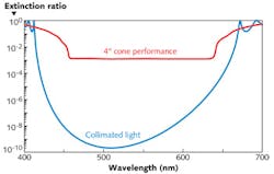
The desired polarizations in such a device are locked to the principal plane of incidence of the cone, while the actual polarization modes of any individual ray are locked to its local plane of incidence; for skew rays out of the principal plane of incidence, these are not the same. The result is polarization leakage that limits the performance of the device. It is a geometrical effect that depends purely on the principal angle of incidence Φ and the cone semi-apex angle, Φ (both measured at the coating); the limiting extinction ratio that cannot be exceeded is given to a good approximation by Φ2/(4tan2 Φ) with Φ in radians.1
Figure 1 shows a comparison between an ideal polarizer performance at 45° incidence in collimated light and in a 4° cone of illumination. The degraded performance in the cone is virtually that predicted by the formula.
It is clear from the formula that a move to still higher angles of incidence would improve the performance in an illuminating cone. A move to 63° would improve performance by a factor of four. But this implies a more difficult system design involving rather more glass, and as a result, the 45° incidence angle is much preferred by system designers.
Uniformity problems
The uniformity of deposition thickness in a coating machine follows laws similar to those of illumination; techniques of masking, along with moving substrates and even sometimes sources, are used to reach the necessary uniformity targets. Even with the best attention to detail and the most advanced equipment, there can be residual variations in thickness across a coated part; these can sometimes have unexpected consequences. Like the polarization effects described earlier, these effects are completely calculable by a suitable computer model.
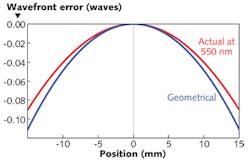
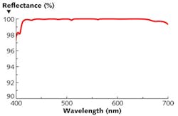
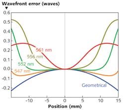
We can illustrate some of the sometimes-unexpected effects on optical performance by examining two different front-surface thin-film-interference reflecting coatings. We shall assume that these coatings are deposited over a completely flat substrate of 30 mm diameter and that there is a radial error in the thickness of the coating such that the resulting surface is spherical with a drop from center to periphery of about 2%. We assume that the parts are illuminated at normal incidence by a perfectly collimated monochromatic wave. Geometrical considerations tell us that the resulting wavefront should now be ellipsoidal with a variation of exactly double that in the coating.Although the fundamental model of thin-film interference has been with us for a long time, innovations and elaborations are still being made. Software products that do the calculations for us and in so doing free us from the massive burden of calculation are far from static. The calculations in this article were all carried out by the Essential Macleod software package for thin-film design, manufacture, and analysis.
REFERENCE
1. A. Macleod, "Thin film polarizers and polarizing beam splitters," Society of Vacuum Coaters Bulletin, Issue Summer, 24–27 (2009).

Dr. Angus Macleod | President and CEO, Thin Film Center
Angus Macleod is President of Thin Film Center Inc, Tucson and Professor Emeritus of Optical Sciences, University of Arizona. He was born in Scotland and after graduating from the University of Glasgow he worked in research, development, engineering, production and management for several UK companies. He was Reader in Thin-Film Physics at Newcastle-upon-Tyne Polytechnic (now University of Northumbria) from 1971 and professor of Optical Sciences at the University of Arizona from 1979. In 1995 he retired from the University to devote his full attention to Thin Film Center. His technical interests are primarily in optical coatings, their design, analysis and production. He has over 200 publications in the area of optical coatings but is probably best known for his book “Thin-Film Optical Filters,” now in its fourth edition.
