BEAM STEERING: Parallel projection galvo scanning enables materials processing of freeform surfaces

YU CAO and DEHUA ZHU
Galvanometric (galvo) scanners are high-performance rotary motors that direct highly focused lasers beam onto an x-y plane, with primary areas of application being the fast and precise positioning of laser spots to scribe text, barcodes, and other various graphics onto the flat surface of a production line component. Since the galvo scanning method requires the intended target to be two-dimensional (2D), how to handle laser materials processing on uneven or freeform surfaces has become a key challenge for the laser-based manufacturing industry.
A common solution is the three-dimensional (3D) galvanometer scan system. Typically, a mechanical linear slide is installed in place of a fixed mounting structure. The linear slide can either be controlled via an external software package run on an industrial PC or—in the case of some slightly more sophisticated laser heads—controlled by the actual laser unit itself. The latter laser heads, namely three-axis control technology introduced by Keyence (Itasca, IL) and SCANLAB (Munich, Germany), take the existing x-y plane galvo-mirror configuration and apply it to the z-axis using a sliding laser expansion lens.1,2 As the expander moves closer to the laser output, the focal point of the laser does as well.
In essence, this creates a zoom optical system that enables laser materials processing on the uneven surfaces that have been previously untouchable within the focal range of the laser beam. Unfortunately, this zoom galvanometer scan system still cannot be directly applied for scanning space curves upon freeform-shaped parts.
An alternative scanning technique developed at Wenzhou University is our parallel projection galvanometer scanning (PPGS) method, which represents a low-cost, flexible, macro- to micro-scale solution for laser materials processing on freeform surfaces.
The PPGS parallel projection transformation maps 3D space curves to terraced 2D plane graphics that are suited to traditional galvanometer scanning methods. The existing 3D galvanometer scan system, the "3+2" method, and rob-scan systems, as we will describe, are alternative choices for different application situations.
PPGS principle
The PPGS method for laser materials processing on freeform surfaces is based on two principles. First, every optical focus system has a depth of focus (DOF) in which the cross-section shape, size, and energy distribution characteristic of the laser beam remain constant. Alternatively, "processing depth of focus" or PDOF corresponds to and takes into account the topographical unevenness on the part surface for which the laser processing parameters and effects are essentially the same. Note that PDOF varies with the type of application and process precision requirements; generally, PDOF = (0.8 to 1.2) × DOF.
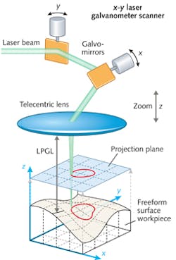
Second, in linear algebra and functional analysis, a graphical projection leaves its image unchanged.3 If a linear transformation P from a vector space to itself is defined as idempotent, meaning that P2 = P, the transformation is reversible; parallel projection is one such kind of graphical linear transformation that is reversible. For PPGS, we use orthographic parallel projection in which the projection rays of the laser beam from the object to the projection plane are parallel to each other and perpendicular to the projection plane. When mapping 3D graphical points on freeform surfaces to a 2D plane, reversible laser scanning is accomplished through a PPGS optical system that uses the combination of galvo scanning and a telecentric lens (see Fig. 1).
In the PPGS system, the graphics on a freeform surface are parallel-projected to the focal plane of a telecentric lens. The laser is directed along the space-curve path on the freeform surface part without deviation by x-y axis galvo scanning of the mapping graphic path on the parallel projection plane. The PPGS process flow involves six steps:
Step 1: Choosing the PPGS system. An analysis is made for the specified laser materials processing need that identifies the appropriate x-y laser galvo scanner and telecentric lens that provides the desired scan range, focal length, and PDOF value.
Step 2:Installation of the freeform surface part. The freeform part to be processed is placed in a fixed position in the x-y-z coordinate of the PPGS system.
Step 3: Division of the freeform surface graphics. Here, the part is divided into sub-blocks—projection units that can be subsequently scanned by traditional 2D (x-y plane) galvo scanning systems. The division is based on the maximum deviation of the z-coordinate value inside the sub-blocks, which is less than the PDOF. Based on the outline of the divided sub-blocks, graphics composed of space curves to be scanned on the part are split into sub-block curve-line graphics. Obviously, different types of topography-partition algorithms such as contour-line generation can be used in this step.
Step 4: Calculation of the laser processing focal length (LPFL) of each sub-block. The LPFL values are computed as the average z-coordinate value within a sub-block to make sure the laser beam is focused on the surface of a workpiece within the PDOF.
Step 5: Parallel projection of freeform surface graphics to the x-y plane. Parallel projection of the graphics inside the respective sub-blocks to the focal plane of the telecentric lens simply means mapping the point (x, y, z) of the freeform surface graphics in 3D space (R3) to the point (x, y, 0) of the x-y plane. The obtained x-y projection graphics of each sub-block will be used as the x-y laser galvo scanning paths in the next step.
Step 6: Laser galvo scanning of graphics in sub-blocks. Finally, the axial distance between the telecentric lens and an arbitrary unprocessed sub-block is made equal to its LPFL by using a zoom optical system or by positioning the laser head. The laser spot is scanned according to the x-y projection graphics of the sub-block through the laser galvo's x-y scanning motion, and all sub-block paths are traversed until the entire surface is processed.
This procedure is based on the assumption that the part size fits within the laser galvo scan range. If the size is beyond the range, the operator must first divide the freeform surface into several sections—each smaller than the scan range—and then one-by-one complete the previous steps.
Applications
The PPGS method means that expensive robots or five-axis machine tools are no longer a requirement. Through parallel projection algorithms, complex freeform curve programs that traditionally involve five-degree-of-freedom (x, y, z, and rotation about x and z) systems are reduced to a three-axis (x, y, z) coordinate frame.
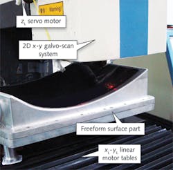
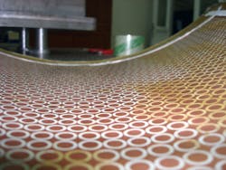
We have developed a simple "3+2" axis PPGS system in which a 2D galvo scanning system (containing the x-y laser galvo scanner and telecentric lens) is fixed at the laser processing head, which is then mounted on a zL-axis mechanical slide for positioning in the focal plane (see Fig. 2). Here, L represents the linear motion of the worktable, which is different from the x-y galvanometer scanning motion. The part with a freeform surface is fixed on the xL-yL working table; thus, "3+2" incorporates the orthogonal xL-yL-zL linear motion framework, plus the x-y galvanometer scan motion.For this texturing example, the projection dimension of the workpiece is 450 × 450 mm; the scan range of the galvo system is 40 × 40 mm; DOF is 0.06 mm; and the chosen PDOF = 1.2 × DOF or roughly 0.07 mm. Using a contour division algorithm and 3553 sub-blocks, the periodic arrays of metallic elements fabricated by the PPGS method have good uniformity with a maximum cell-spacing error of 0.06 mm and maximum shape dimension error of 0.03 mm.
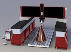
For micro- to macro-scale laser materials processing of ultra-large freeform surfaces—for example, the creation of super-hydrophobic microstructures on the surface of aerofoil and ship engine blades—the PPGS technology can be blended with a robotic manipulator (see Fig. 4). Using a gantry structure as the framework of a CNC machine tool, a robotic manipulator is installed at the position of the original spindle on which the PPGS unit is installed. In this case, the system is called a "rob-scan" device for materials processing on the fly.In rob-scan applications, the position and orientation of the PPGS unit relative to the part coordinates can be flexibly adjusted by the robotic manipulator such that the projection direction of the PPGS algorithm can be changed accordingly. This real-time adjustment optimizes the PPGS algorithm efficiency, making precision materials processing possible.
ACKNOWLEDGEMENTS
This work was supported by the National Natural Science Foundation of China (Grant No.51005083, 51375348).
REFERENCES
1. J. P. Jelonek, Industrial Laser Solutions, 23, 8, 30–33 (2008).
2. J. Gottmann et al., J. Laser Micro. Nanoeng., 4, 3, 192–196 (2009).
3. C. D. Meyer, Matrix Analysis and Applied Linear Algebra, Society for Industrial and Applied Mathematics, Philadelphia, PA, 386–387 (2000).
Yu Cao and Dehua Zhu are associate professors at the College of Mechanical & Electrical Engineering, Wenzhou University, Wenzhou, Zhejiang Province, China 325035; email: [email protected]; www.wzu.edu.cn.


