NICOLAUS HETTLER and ROBERT HUTCHINS
Head-up displays (HUDs) were initially developed some 50 years ago for military and aerospace applications and were initially used only in the cockpits of multimillion-dollar jet fighters. While the original interest for automotive applications was primarily in the luxury segment, HUDs are now also advancing into family and other mid-range vehicle applications.
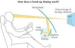
For automotive applications, there are three basic implementations for HUDs: re-emissive, which is a direct-write approach; combiner, which is based on light reflected off a semitransparent screen; and reflective, which is based on light reflected off the inside of the windshield (see Fig. 1).
The re-emissive type involves writing the image on the inside surface of the (perhaps coated) windshield so that, via scattering or emission, it is visible to the driver. This approach boasts significant advantages in terms of addressable screen area, resolution, color gamut, luminance, and image correction, but it cannot place the image over the front of the car-something many consider to be the vital feature of a HUD, as it minimizes driver distractions away from the road.
The latter two approaches are effectively the same in terms of the overall optical layout. The combiner type can be built more compactly and at lower cost, but both approaches are the technology front-runners, primarily because they do allow the realization of an effective image somewhere over the front of the car.
Certainly one of the most crucial aspects of HUD design is the choice of light engine, be it a thin-film-transistor (TFT) display,1 a digital micromirror (DMD)-based unit,2 a MEMS scanning mirror,3 or other approach.4 Nonetheless, there are aspects to the optical layout, particularly in a non-luxury automotive application, that make the choice of optical components equally crucial.
What is so special about automotive?
While the market for HUDs in commercial and civil aviation still dominate (and these will continue to be installed on a large scale), their potential in other markets is becoming increasingly interesting for technology developers.
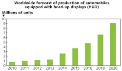
In 2012, just 2% (1.2 million) of automobiles sold worldwide had HUDs installed. Japan has had the highest number of installed automotive HUD systems in recent years, with Asia and the Pacific exhibiting the highest regional growth rate. Europe is, however, expected to take the lead by 2020, as it currently provides the majority of new developments for adoption of the technology in the non-luxury segments (for example, German manufacturer Continental has been supplying HUDs for BMW's midrange 3-series since 20125).
Market studies indicate a compound annual growth rate (CAGR) for this market of close to 30% through to the end of the current decade, translating to an overall market growth of approximately a factor of six; around 9 million HUD-equipped vehicles (roughly 9% of the market) will be sold in 2020 (see Fig. 2). Needless to say, given the typical components in a HUD system-light engine, projection optics, display panel, and others-this is also a growing market for photonics component manufacturers.Specific issues in automotive design
Notably, the developments visible for pico- and microprojector technology provide some of the driving factors for HUD development, in that many of the requisite specifications are mirrored in both applications. Advanced HUDs draw on these synergies and also allow users to access key information at a convenient viewing distance, thus allowing them to concentrate more on their driving and also providing additional driving comfort.
But there are issues specific to automotive applications, including system configuration and ease of reconfigurability for different car models, as well as environmental/performance issues (consider the range of temperature and humidity environments in which automobiles are used). Then there is the stipulation for compliance with automotive quality management standards such as TS16949,6 and lastly that one performance specification common to all automotive subsystems: namely, absolute high-performance reliability at next to no cost.
Projecting the display
To demonstrate the optical issues present in HUD design, consider an approach with a light engine consisting of a high-resolution TFT-LCD display with luminance and color gamut provided by high-intensity backlight LEDs.
The picture-generating unit (PGU) is located below the dashboard and underneath the windshield. The subsequent optics must project the image upward and off the reflecting surface (combiner/reflector), at the same time giving the impression that the image is floating somewhere over the front of the car at a distance of around 1.5 to 2 m from the driver for combiners, or marginally farther for reflective types.
The task of projecting a display of this nature and providing for magnification and image location is trivial. Common specifications are for a pixel size of 30 μm and up in a widescreen format and over a field of view (FOV) for the driver of up to 5°. Conventional macro-optics would suffice here, with the caveat that they add unnecessary bulk to the system.
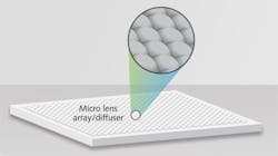
The projection/magnification is thus preferably accomplished with a microlens array (see Fig. 3), in the simplest case with one lens for each three-color pixel of the TFT display. Adequate manufacturing and bonding precision sufficient for accurate image rendering with minimal loss in quality is readily available, and this type of array element can be manufactured with varying degrees of effort using any number of processes and materials-direct machining or molding of glass, replication on glass, molding of plastics, and so on.Given the right conditions, the one-lens-per-pixel approach would actually be the ideal solution-that is, were it not for the fact that automotive interior environments are subject to considerable extremes of temperature (-50 to +70°C) as well as vibration. Additionally, the automotive industry has high expectations regarding uniformity (that is, pixel grain and overall luminance) and contrast (reduced through non-guided light) over a wide range of lighting conditions.
Effectively, guaranteeing alignment over the lifetime of the vehicle and over wildly differing climates is difficult. Even minor (for example, thermally induced) misalignments introduce image artifacts such as diffraction and/or moiré effects, thus degrading the quality of the observed image over time and/or temperature.
The workaround here is to reduce the lens size so that each color pixel is projected by multiple microlenses. At this stage, however, there is a trade-off in lens size to consider: too small and it starts to behave like a diffractive aperture, but if it is too large, there is insufficient lens sampling per pixel in order to suppress grain.
For the pixel sizes commonly used, a 3×3 microlens subarray per pixel can be readily achieved and is sufficient for most uses. For PGUs sensitive to diffractive effects, 4×4 subarrays, random shifting of the subarrays, and pseudorandom lens sizes can all play a role in improving performance-misalignment simply micro-shifts the subset of randomized microlenses seen by each pixel.
This type of element is then not so easily manufactured using all available process technologies, in particular in the volumes projected for the end of the decade. All things considered, an injection-molded plastic lens array properly satisfies all of the optical performance requirements and additionally fulfills those relating to volume manufacturability, cost, weight, and bulk.
Confusingly, from an optics standpoint, this element in this application is often termed a "diffuser".
Nanostructuring and stacking for further functionality
Aside from the obvious benefits of optical plastics as a material, there are further advantages that draw on the flexibility of its molded manufacture.
The projection optic described above is effectively reduced to a 0.6 to 1.2 mm substrate sporting pseudo-randomized microlenses on just a single side with a sag of up to 50 μm. The other side of the substrate is thus still free to accommodate further optical functions.
For example, nanostructures that mimic the so-called moth-eye effect—thereby generating a broadband antireflection effect—can be readily stacked onto the second surface and thus neatly provide a route to optimizing the optical transmission through the diffuser. The same is true for a number of other surface structures-Fresnel lenses, binary or multilevel diffractive surfaces, true diffusing surfaces, and even reflectors. Moreover, if the supplementary nanostructure is small enough, it can even be directly written onto the (comparatively macro) refractive surface via appropriate machining of the master.
Production of all these complex refractive and additional subwavelength nanostructures with the necessary structural precision (about 300 nm) and positioning accuracy (about 1 μm) requires a heavily modified mastering and injection-molding approach, coupled with subsequent multistep microfabrication and post-processing to provide additional capability (for example, stacking).
Multiple alternate opportunities now arise for these so-called multi-μ-functional solutions in plastic, for example in applications such as optofluidics, optoelectronics, and in structured lighting for industrial vision, as well as for clinical point-of-care, diagnostics, environmental monitoring, and biochemical/forensic screening. Typical materials include polycarbonate, PMMA, and cyclo-olefin-copolymers; these provide almost all the optical and functional performance aspects offered by glass, but are additionally lighter, lend themselves to high-volume replication via injection molding, and are more cost efficient.
The future for HUDs
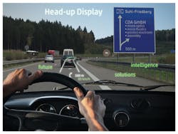
The development of the HUD market will of course be accompanied by continuing advancements in performance. A larger FOV for the driver (10° and up) coupled with higher-resolution light engines provide for greater content scope. Couple this with higher luminance and better color gamut (thus allowing a greater diversity of content to be visible in varying conditions), and the next step for HUDs is augmented reality and advanced driver-assistance systems (ADASs; see Fig. 4). Also, at some point in HUD development, we will probably see a transition away from flat-panel displays to DMD-based light engines.2Regardless of the light engine finally chosen, all these specifications lie within the available performance spectrum of the plastic optical components discussed and can be neatly accommodated by appropriate modification to the design of the diffuser structure.
REFERENCES
1. "Continental now supplying head-up displays to two premium automotive manufacturers," Continental Automotive; http://www.continental-corporation.com/www/pressportal_com_en/themes/press_releases/3_automotive_group/interior/press_releases/pr_2012_03_22_hud_bmw_en.html.
2. "Enabling the next generation of automotive head-up display systems," Texas Instruments; http://www.ti.com/lit/an/dlpa043/dlpa043.pdf.
3. "MEMS scanning mirror," Lemoptix; http://www.lemoptix.com/technology/mems-scanning-mirrors.
4. A. Olwal, "Next generation head-up displays," http://web.media.mit.edu/~olwal/projects/research/huds/olwal_next_gen_huds_2005.pdf.
5. "The head-up display reduces driver distraction and increases driver safety," Continental Automotive; http://continental-head-up-display.com/.
6. "Welcome to TS16949.com," http://www.ts16949.com/a55aeb/ts16949.nsf/layoutB/Home+Page?OpenDocument.
Nicolaus Hettler is managing director and Robert Hutchins is senior optical designer at CDA GmbH, Suhl, Germany; e-mail: [email protected]; www.cda-microworld.com.


