Lens-design Software: Freeform LED lens-design approach produces high uniformity
One of the most actively developed uses for freeform optics right now is as light collectors and uniformizers for spotlight and directional-floodlight general-illumination LEDs. Due to a diffuse—and often nonrotationally symmetric—directional light output, a bare white-light LED device itself (usually consisting of a flat blue LED with a layer of yellow YAG phosphor), while very bright, cannot efficiently serve as a floodlight illuminator; it needs to be paired with optics. Freeform optics, with their many tweakable degrees of freedom, are an ideal choice.
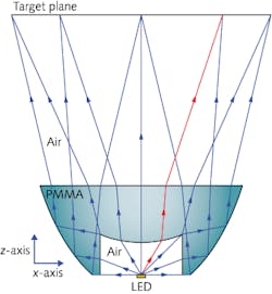
Researchers at the College of Optical Sciences and the Department of Physics at the University of Arizona (U of A; Tucson) have developed an LED freeform illumination lens-design approach called composite ray mapping that boosts illumination uniformity over existing LED lens designs; the design is also more robust (less sensitive to manufacturing errors).1 As do some other LED illumination optics, the U of A design combines refractive and reflective (via total internal reflection, or TIR) surfaces (see figure).
High uniformity and throughput
One prime aim of a good freeform optical design for LED floodlighting is to achieve good intensity uniformity throughout the floodlit area; another is maximizing light throughput. The optimization calculations that must be done to attain high uniformity are not trivial; done rigorously, they often require use of the “tedious Monge–Ampère second-order nonlinear partial differential equation” as the U of A researchers call them.
The conventional approach to simplifying design optimizations that include both refractive TIR surfaces is called ray mapping; however, while easing the calculation load, ray mapping has deficiencies that lead to surface errors that are a strong function of the selected ray mapping.
The composite approach taken by the U of A group samples the light distribution for the refractive and TIR sections of the optic in different coordinate systems, superposing the resulting light from the two regions. Starting with a 1 × 1 mm LED chip, the design produces a uniform 550 × 550 mm square field 800 mm away from the 20-mm-thick, 45 × 45 mm freeform lens.
To check the uniformity of the lens via simulation, five million rays were traced using LightTools (Synopsys, Mountain View, CA). The resulting nonuniformity, including the rays collected via both refraction and TIR, was 8.0% using the relative standard deviation method. The total energy collected by the optic and directed to the floodlit plane was 90% of the energy emitted by the LED, even when accounting for Fresnel losses. In addition, inducing variations in refractive index into the calculations showed a reduction in sensitivity to manufacturing errors of more than a factor of two relative to previous freeform designs.
REFERENCE
1. Donglin Ma et al., Appl. Opt. (2015); http://dx.doi.org/10.1364/AO.54.000498.

John Wallace | Senior Technical Editor (1998-2022)
John Wallace was with Laser Focus World for nearly 25 years, retiring in late June 2022. He obtained a bachelor's degree in mechanical engineering and physics at Rutgers University and a master's in optical engineering at the University of Rochester. Before becoming an editor, John worked as an engineer at RCA, Exxon, Eastman Kodak, and GCA Corporation.
