Nanoscale Imaging: Tabletop high harmonics illuminate the nano-world
DANIEL E. ADAMS, CHRISTOPHER S. WOOD, MARGARET M. MURNANE, and HENRY C. KAPTEYN
An abiding theme for 21st-century technology is smaller and faster. Nanotechnology has become a major driver for our economy, as current-generation electronics employ feature sizes as small as 14 nm—a small fraction of the wavelength of visible light. However, this relentless advance presents major challenges, as it becomes more and more difficult to see what we can make.
A variety of advanced optical imaging techniques such as STORM, STED, and PALM microscopy (recognized in the 2014 Nobel Prizes) push microscopy to sub-diffraction-limited resolution, and electron microscopy can resolve atomic-scale features. However, these techniques all have serious limitations—in the requirement for fluorescent labeling or extensive sample preparation, in contrast and elemental identification, and in the ability to capture dynamics. To date, no technique can capture function in 3D nanosystems, a capability that would aid immensely in iterative design and optimization.
Fortunately, the 21st century has brought great advances in two relatively new technologies: high-harmonic generation (HHG) and coherent diffraction imaging (CDI). As a result, a new generation of powerful nanoscale coherent imaging techniques are emerging that present major advantages compared with other approaches: the ability to image with amplitude and phase contrast—in 3D and at the wavelength limit; extremely efficient use of illumination; inherent elemental and compositional contrast; the ability to image opaque structures; and the ability to capture heat, spin, and charge flow in new materials and nanosystems that promise to dramatically increase the switching and read/write speed and efficiency of nano-devices, with 10 fs time resolution.
Coherent short-wavelength light sources and coherent imaging
The same revolution that ultrafast visible lasers underwent in the 1990s is now happening for tabletop high-harmonic sources. These advances are fueled both by new understanding of the limits of extreme nonlinear optics, as well as new high-average-power infrared lasers. HHG is the most extreme nonlinear-optical process observed to date for up-shifting femtosecond laser light to much shorter wavelengths, spanning the entire electromagnetic spectrum from the ultraviolet to soft x-rays. Essentially, the result is a tabletop x-ray laser, generating a rainbow of deep-UV to x-ray wavelengths simultaneously and emitting spatially coherent beams, with femtosecond to attosecond pulse durations.
Our understanding of the HHG process has revealed the broad potential of this technique as a light source. Until recently, bright HHG sources were thought to be possible only for wavelengths longer than ~10 nm (hv <150 eV), and could be generated only with linear polarization. Now we know how to generate bright HHG well into the soft X-ray region, to photon energies >1.5 keV (corresponding to wavelengths <8 Å),1 and with either linear or circular polarization.2 Moreover, HHG is perfectly synchronized to the driving laser.Thus, high-harmonic beams are an ideal light source for coherent diffraction microscopes, producing a comb of well-separated harmonics that can be spectrally filtered or multiplexed. The HHG light source is complementary to large-scale synchrotron and x-ray free-electron laser (XFEL) sources, making possible higher time resolution and tabletop access.
CDI is a computational imaging technique, sometimes called lensless imaging. In CDI, rather than illuminating an object and then creating an image on a detector using a lens, one simply illuminates an object and captures the scattered light directly with a detector. An advanced phase retrieval algorithm then substitutes for the lens to retrieve the image.
CDI generally requires coherent (i.e. laser-like) illumination, but its lensless nature makes it an ideal match for x-ray imaging. This is due to challenges in fabricating x-ray image forming optics, which must be diffractive in nature and which typically limit the resolution to ≈ 25 nm. The combination of HHG and CDI eliminates the image forming optics, making it not only possible, but quite straightforward, to obtain wavelength-limited resolution for the first time in the EUV and ultimately the x-ray regions of the spectrum.
CDI was first demonstrated in the late 1980s,3 with the first application to x-rays in 1999.4 CDI is a very general imaging technique that can use any coherent source, including electrons. It is the most photon-efficient imaging method possible since no optics are needed between the sample and detector, allowing for very high-numerical-aperture imaging (>0.6).
Leveraging this rare convergence of coherent tabletop sources, advanced algorithms, and coherent imaging techniques, a team from JILA and UCLA set a world record for any light-based tabletop microscope by imaging a test pattern with 22 nm resolution.5 Figure 1 shows the very simple setup required for coherent diffraction microscopes—either in transmission or reflection.
Next-generation coherent microscopes
Scanning electron microscopy (SEM) and atomic force microscopy (AFM) are well-established techniques for imaging surfaces with nanometer resolution. CDI provides complementary information with several added benefits such as elemental selectivity, non-destructive long working distances compared to AFM, and without the surface charging effects in SEM. CDI is a reference-less, simultaneous phase and amplitude imaging technique capable of producing high-contrast, high-fidelity images in both reflection and transmission, with nanometer transverse resolution.
In reflection, the contrast mechanism in CDI is a threefold combination of absorption- and geometric/material-dependent phase shifts that can produce images with sub-nanometer axial resolution. This makes CDI an ideal tool for surface profilometry, as well as 3D tomographic imaging due to the penetrating powers of x-rays.
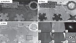
Figure 2 shows a reflection mode image of titanium features patterned on a silicon substrate. Figure 2b is an SEM of the same sample for comparison. The area highlighted by a black rectangle (see Fig. 2b) is magnified and compared in Fig. 2d–e. Fine surface variations that are easily visible in the CDI reconstruction and AFM image (Fig. 2e and g) are all but invisible in the SEM (see Fig. 2f). Figures 2h and i show the reconstructed high-harmonic beam intensity and phase, respectively.The CDI images in Fig. 2 were generated using an advanced and powerful technique called ptychography.6 (EUV HHG is now commercially available via KMLabs, while ptychography is available via Phasefocus). In ptychography, several diffraction patterns are recorded while the sample is scanned perpendicular to the illumination, ensuring significant overlap between adjacent positions. The reconstruction algorithm takes advantage of this increased amount of redundant information and produces images not only of the specimen, but also simultaneously characterizes the high-harmonic beam in amplitude and phase.
Initially suggested as an augmentation to standard electron microscopes that were already taking scanning data, ptychography received a huge boost in efficacy when Rodenburg et al.7,8 refined the algorithm to update both the sample and the illuminating wave, called the probe. In the past, inadequate knowledge of the probe translated directly to imperfections in the sample reconstruction. Thus, with the ability to iteratively solve for both the probe and sample, ptychography has become the premier CDI technique for robust high-fidelity image reconstruction.
Having provided microscopists a new, flexible tool, ptychography is just beginning to reveal its true utility.9 Taking advantage of information redundancy in the multiple (sometimes thousands) diffraction patterns, researchers have found a way to extend ptychography to new regimes of information multiplexing. There is enough data in the ptychographic scan to simultaneously solve for both the specimen and probe as well as a variety of other information such as the true scanning stage positions (often muddled by systematic errors like thermal drift).10
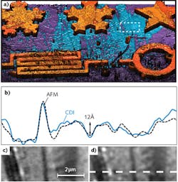
Figure 3a shows the same sample as Fig. 2, but in 3D by taking advantage of the CDI phase (video online). Stage position refinement was performed on the reconstruction shown in Fig. 3 to achieve high-quality imaging. Figure 3b is a profile comparison between AFM and ptychography (Fig. 3c and d, respectively) of the region in Fig. 3a highlighted with a white-dashed rectangle. The two profiles plotted in Fig. 3b agree to within ~6 Å (95% confidence interval) and were taken along the white-dashed line in Fig. 3d. More surprising, ptychography is even powerful enough to deal with multiple spatial and spectral mode illumination and propagation through optically thick, scattering media.11-13Impact and outlook
The combination of HHG and CDI is bringing a new view of the nano-world into focus. The ability to image thick objects with elemental sensitivity, produce quantitative phase and amplitude high-contrast images in both transmission and reflection, and probe dynamic phenomena with femtosecond accuracy in three dimensions gives HHG-CDI a bright future for both science and technology.
While complementary to electron and atomic force microscopies, CDI stands alone as a non-destructive, long-working-distance, high-contrast x-ray microscopy with resolution limited only by the wavelength. With advances in ultrafast lasers (Ti:sapphire, fiber, and direct diode-pumped systems), high-harmonic technology is rapidly developing, enabling robust operation, ever-decreasing form factor, and an increasing range of applications.
The most immediate commercial application will likely be in the area of nanoelectronics, where tabletop commercial systems can address the challenging metrology needs for next-generation nanofabrication. Moreover, high-harmonic sources nicely cover the wavelength ranges of interest for imaging and metrology associated with current and future EUV lithography.
ACKNOWLEDGEMENTS
The authors would like to thank the graduate students, Bosheng Zhang, Matthew D. Seaberg, Dennis F. Gardner, Elisabeth R. Shanblatt, Robert M. Karl, and Christina L. Porter, whose hard work produced the images and analysis found in this article. The authors would also like to graciously acknowledge funding from DARPA, NSF, DOE, and the SRC.
REFERENCES
1. T. Popmintchev et al., Science, 336, 1287–1291 (Jun. 8, 2012).
2. O. Kfir et al., Nat. Photon., 9, 99–105 (2015); http://dx.doi.org.10.1038/nphoton.2014.293.
3. J. N. Cederquist, J. R. Fienup, J. C. Marron, and R. G. Paxman, Opt. Lett., 13, 619–621 (Aug. 1988).
4. J. W. Miao, P. Charalambous, J. Kirz, and D. Sayre, Nature, 400, 342–344 (Jul. 22, 1999).
5. M. D. Seaberg et al., "Ultrahigh 22 nm resolution EUV coherent diffraction imaging using a tabletop 13 nm high harmonic source," Proc. SPIE: Metrology, Inspection, and Process Control for Microlithography Xxvi, Pts. 1 and 2, 8324 (2012).
6. J. M. Rodenburg and H. M. L. Faulkner, Appl. Phys. Lett., 85, 4795–4797 (Nov. 15, 2004).
7. A. M. Maiden and J. M. Rodenburg, Ultramicroscopy, 109, 1256–1262 (Sep. 2009).
8. P. Thibault, M. Dierolf, O. Bunk, A. Menzel, and F. Pfeiffer, Ultramicroscopy, 109, 338–343 (Mar. 2009).
9. J. Miao, T. Ishikawa, I. K. Robinson, and M. M. Murnane, "Diffractive imaging with coherent x-ray sources," Science, in press (2015).
10. F. Zhang et al., Opt. Express, 21, 13592–13606 (Jun. 3, 2013).
11. T. M. Godden, R. Suman, M. J. Humphry, J. M. Rodenburg, and A. M. Maiden, Opt. Express, 22, 12513–12523 (May 19, 2014).
12. D. J. Batey, D. Claus, and J. M. Rodenburg, Ultramicroscopy, 138, 13–21 (Mar. 2014).
13. P. Thibault and A. Menzel, Nature, 494, 68–71 (Feb. 7, 2013).
Daniel E. Adams, Christopher S. Wood, Margaret M. Murnane, and Henry C. Kapteyn are at JILA/University of Colorado Boulder and KMLabs, Boulder, CO; e-mail: [email protected]; www.kmlabs.com.


