Fiber-optic Components: Fiber Y-splitter handles seven-core optical fiber
In the past few years, data-transmission rates for experimental fiber-optic systems has reached deep into the terabit-per-second range. Some configurations that have helped to achieve such rates are a combination of orbital angular momentum (OAM) and wavelength-division multiplexing (WDM), which reached 100 Tbit/s over a short length of fiber; hybrid integration with differential-quadrature phase-shift keying, reaching 14 Tbit/s over a single 160 km fiber; an optical fast-Fourier-transform (FFT) scheme that enabled 26 Tbit/s over a single 50 km fiber; and the use of multicore single-mode fiber, which allowed transmission of 255 Tbit/s over a 1 km fiber length.
The last approach, which often takes the form of a seven-core triangular array, is a relatively straightforward fiber design that can greatly boost data rate (as long as crosstalk between cores is minimized). One thing that is not straightforward about using seven-core fiber, though, is the design of the components that couple light into and out of the fibers, as well as manage the light during transmission. To help in this respect, Ehab Awad of King Saud University (Riyadh, Saudi Arabia) has designed a 2.4-mm-long Y-splitter for multicore fibers that requires no separation of the fiber's multiple cores.
Numerically simulated
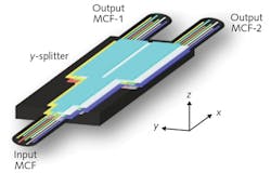
The design, which so far has been numerically simulated for a seven-core fiber but not yet constructed, relies on a number of differing Y-splitting waveguide layers—one for each core—with all layers having a novel double-hump graded-index (DHGI) profile that splits optical power equally into two halves (see figure). The input and two output fibers are rotated about their axes with respect to the Y-splitter until all of the seven cores reside in different horizontal planes with respect to the splitter. This allows a separate waveguide layer to access each of the seven cores.
Each single Y-splitter layer contains an expander, a DHGI space-division splitter (SDS), and a separator. The seven individual Y-splitters are surrounded by a 400 × 125 μm cladding region. The fiber in the numerical model has seven identical step-index single-mode cores with a 40 μm separation between adjacent cores, a cladding refractive index of 1.45, and a core refractive index of 1.4551.
Each splitter has a waveguide height of 9 μm, is separated from the adjacent waveguide layer by 4 μm of cladding, and splits the input light into two outputs separated by 250 μm (twice the diameter of the multicore fiber). The input and output fibers are rotated by 19° about their axis to create a line-of-sight view between cores of each single splitter.
The waveguide lens embedded in each splitter layer is 280 × 60 × 9 μm in size and has a gentle parabolic refractive-index profile that expands the beam adiabatically to minimize the production of higher-order modes. Light from the lens enters the DHGI SDS portion of the device, which has two parabolic graded-index humps, each with a size of 995 × 60 × 9 μm. The dimensions are sized to reliably split the input beam 50%/50%. The two beams are then sent to two separate waveguides and then on to the two output fibers.
In the process of designing the Y-splitter, Awad ran finite-difference time-domain (FDTD) simulations of the electromagnetic-field distribution in the device and associated optical fibers at 1555 nm and other wavelengths, as well as eigenmode expansion (EME) solutions using software from Lumerical Solutions (Vancouver, BC, Canada). These simulations showed no significant cross-coupling between waveguide layers or cores.
The simulations indicated that the splitter would work well over a broadband region from 1460 to 1675 nm with polarization-insensitive operation, showing an insertion loss of around 0.12 dB over all wavelengths, excess loss of 0.13 dB, polarization-dependent loss of less than 0.02 dB, and a worst-case return loss of 35.8 dB. The optimum 3 dB splitting ratio fluctuated by less than 0.1 dB over the entire wavelength range. A tolerance analysis showed that low-loss performance was achieved for maximum misalignments of about 0.5 to 1.0 μm (depending on the type of loss modeled).
REFERENCE
1 E. Awad, Opt. Express (2015); doi:10.1364/OE.23.025661.
About the Author
John Wallace
Senior Technical Editor (1998-2022)
John Wallace was with Laser Focus World for nearly 25 years, retiring in late June 2022. He obtained a bachelor's degree in mechanical engineering and physics at Rutgers University and a master's in optical engineering at the University of Rochester. Before becoming an editor, John worked as an engineer at RCA, Exxon, Eastman Kodak, and GCA Corporation.

