Aspheres: Precision glass molded aspheric lenses: Design for manufacturing
Precision glass molding (PGM) of aspheric lenses was first introduced to the market in the early 1980s. Since then, the process has gained widespread acceptance in numerous markets from telecommunications and digital still cameras to thermal imaging. The adoption has largely been driven by PGM's ability to provide very repeatable, high-surface-quality glass optics with aspheric surfaces in high volume at low cost. This combination provides a value proposition not readily achievable with any other manufacturing process. To effectively implement this technology in an optical design, it is important to incorporate design-for-manufacturability (DFM) concepts that take full advantage of the benefits that PGM offers.
The precision glass molding process is an isothermal compression molding process.1,2 A brief description of the PGM process follows-the process starts with a glass preform, which is introduced between a set of molds in a precision glass molding machine. These molds replicate the desired surface on the finished lens and are compensated for the thermal molding profile and glass and tooling properties. The molding machine is purged with nitrogen (or sometimes vacuum), and the preform and tooling is heated. Pressure is applied and the mold is allowed to cool, resulting in a finished lens.
Choose the correct material
The most important step in almost any DFM effort is to select the correct material. This is no less important in precision glass molding. The proper selection of the right moldable optical glass can increase performance, decrease lead times, and significantly lower cost. There are more than 200 moldable glass types to choose from, giving the optical designer extensive design freedom.1 However, consideration of manufacturability, availability, and cost can greatly reduce this freedom and limit the solution set. A discussion on material selection with the supplier can help pinpoint the most-effective solution.
It is best to start with an initial selection of one or two glasses and then get feedback from the manufacturer early in the design process, which saves time and cost. Manufacturers will standardize on a select group of materials to achieve economies of scale that can subsequently be passed on as a cost savings to their customers. The manufacturers have extensive experience with these materials and will be able to provide insight and familiarity to reduce risk on performance, quality, and schedule.
For instance, particular glass formulations are known to reduce tooling life and increase cost. Glasses that require lower processing temperatures reduce the potential for oxidation of surfaces during the molding process, which can otherwise lead to increased contamination and frequency of cleaning and maintenance. Lower processing temperatures also lead to shortened heating and cooling cycles, which in turn improve processing speeds and throughput, as well as lower energy use and utility expenses.
Understanding PGM's impact
Once the material selection is complete, it is important to understand the impact of the PGM process on the optical design of the system. The thermal history of a glass determines its physical and optical properties. This is why in conventional manufacturing of lenses, the glass is specified by its annealing rate. A coarse-annealed glass undergoes a shorter cooling cycle than a fine-annealed glass, resulting in different optical properties.
To maximize throughput and reduce cost, the PGM process is optimized to minimize the cooling cycle and overall processing time. The cooling rate for PGM is the annealing rate of the finished product. Though not a common practice, PGM lenses can also be post-annealed, but this typically results in increased cost, lead time, and reduction in surface quality.
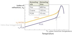
Figure 1 shows a theoretical drop in index of refraction for a moldable glass. While other properties can change as well, such as density and dispersion, index of refraction is the most significant. The typical range of index drop for common moldable glasses used in visible wavelengths (nd) is -0.0006 to -0.010.2Chalcogenide glasses with higher indices exhibit greater drops in the infrared region.3
There are a number of fundamental design concepts that should be implemented into the optomechanical design of a precision glass molded component to follow good DFM practices. The primary consideration should be the overall form factor for the lens—however, this is not as straightforward as it may seem. Precision glass molded lenses come in a variety of shapes and sizes. Diameters can range from less than a millimeter to well over 100 mm, but most are within 1 to 25 mm.
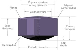
Many different configurations of lens shapes and many different types of glass preforms can be used to make a lens. However, selection of the preform is the manufacturers' responsibility and is usually not part of the design process. The most cost-effective preform for PGM is the ball preform. The design rules that follow are for ball preforms. Many advanced or nontypical shapes or forms can be achieved by using different preform geometries other than balls. Do not be dissuaded from using these types of designs, but rather discuss them early with the manufacturer. Regardless of the shape or size of a PGM lens, the features or nomenclature are essentially the same. Figure 2 defines the physical features of a biconvex lens.The center thickness (CT) of a lens is largely dependent on its overall shape or aspect ratio. Very thin CTs down to 0.2 mm can be manufactured, but may require near-net-shape preforms to reduce the stress in the glass. Large CT values should also be avoided to minimize thermal gradients in the optics.
If the thermal profile of the molding process is not carefully controlled by the manufacturer, excessive thermal gradients can induce stress birefringence, inhomogeneity of the index of refraction, and possible fracture because of thermal stress. Very small edge thicknesses (ETs), such as <0.4 mm, may cause edge chipping and can make the lens difficult to handle or mount into a system. The outer diameter (OD) can be limited by the manufacturer's mold tooling design, which can range from <1 mm to >25 mm.Very large ODs, like the CTs discussed above, can also be subject to thermal gradients that can negatively affect yields. The aspect ratios of OD to CT (and ET) should also be considered based on the manufacturer's experience with a given glass and mold tooling to maintain the highest possible yields. Aspect ratios are highly dependent on the lens shape, so general rules of thumb are difficult to provide. For instance, aspect ratios for plano-concave lenses can be very large while a typical biconvex lens should be kept under 5.
The sag depth (or height) is the height of the lens surface profile from the apex of the lens to the outer flat flange (highest to lowest point on the surface). The clear aperture (CA), which is sometimes referred to as the optical or effective diameter, represents the portion of the lens described by the lens prescription (such as radius of curvature, conic, and asphere coefficients), where light will propagate for the intended optical function of the lens.
Blend radii and transition zones
The physical aperture (PA), or sag diameter, is where the lens sag ends and the outer flat flange begins. The physical aperture should always be larger than the clear aperture because the convergence of the optical surface and the flat requires the use of a blend radius. This radius is required to reduce the stress concentration and to provide a relief for the radius of the cutting tool. The size of the blend radius depends on the particular surface and manufacturing method used to make it. The PA may also be obscured by the blend radius and may not be able to be measured explicitly.
In some cases, a transition zone between the CA and the blend radius is necessary. The purpose may be to increase the sag diameter to relieve constraints on the mold tooling and ensure that the optical surface is not compromised within the CA. The transition zone can be an extension of the lens surface prescription beyond the CA. However, if this causes a severe aspheric departure outside the CA, a different geometry can be used, such as a tangent line, to connect the CA to the blend radius.
Another parameter to consider is the slope of the optical surface, both within the CA and extending out to the PA. High slopes create difficulty in both mold manufacturing and metrology. Precision diamond grinding is limited to just under 55°, although the actual number may vary based on final geometry and manufacturer. Typical surface profilometers are also limited to 55–60° slopes, and the measurement accuracy can decrease with increased slope of the lens surface. Some stitching profilometers are available as a method to measure steep slopes, but stitching introduces its own set of challenges for accuracy and precision.
Steep geometries (both slope and high curvatures) can also lead to gas entrapment and may require vacuum molding. At the other extreme, lens surfaces with very low slopes and curvatures may increase the risk of misalignment between the mold and ball preform during the molding process. Therefore, the preform must be properly matched to the base curvature of the lens surface to avoid trapped gas while also maintaining proper alignment.
Unless post-processed, a PGM lens will have edge or corner radii. This area is the relief area in the molding process, which compensates for the variations in the volume of the preform. This means the edge radii need to be accounted for in the optomechanical design.
Flanges and insert molding
Mounting features can be molded directly into a PGM component. Flanges are typical on PGM lenses, and these allow for easy mounting. The blend radii and the edge radii must be taken into consideration when implementing flanges.
To have an adequate mating area for assembly, the flanges may need to be extended to account for these radii. Lenses having an excessively large flange will have a larger preform volume, leading to increased material cost. However, flanges are always desirable because it is difficult, and sometimes nearly impossible, to extend the physical aperture to the edge of the lens. Extending the physical aperture to the edge generates a sharp tooling condition and leaves no allowance for an edge radius. A designer should always take into consideration the impact of the optomechanical design on the tooling design.
Another option that can be considered is insert molding, or directly molding the lens into a metallic holder. Insert molding has its own unique design considerations and should be reviewed differently than a standard PGM lens.4
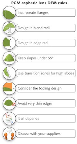
Involving your supplier early and using these DFM techniques when designing a precision glass molded aspheric lens will result in a cost-effective, highly manufacturable design (see Fig. 3).
REFERENCES
1. A. Symmons, Molded Optics: Design and Manufacture, Chapter 5, CRC Press, Taylor and Francis Group, London (2011).
2. A. Symmons and M. Schaub, "Field Guide to Molded Optics," Appendix A, SPIE Press (2016).
3. J. Novak et al., "Investigation of index of refraction changes in chalcogenide glasses during molding processes," Proc. SPIE, 8896, Electro-Optical and Infrared Systems: Technology and Applications X (Sept. 2013); doi:10.1117/12.2028902.
4. A. Symmons and B. Auz, "Design considerations and manufacturing limitations of insert precision glass molding (iPGM)," Invited Paper, Polymer Optics and Molded Glass Optics: Design, Fabrication and Materials III (Aug. 2012); doi:10.1117/12.932253.
Alan Symmons | Executive VP of Operations, LightPath Technologies
Alan Symmons is executive VP of operations at LightPath Technologies (Orlando, FL).
Jeremy Huddleston | Optical Engineering Manager, LightPath Technologies
Jeremy Huddleston is optical engineering manager at LightPath Technologies (Orlando, FL).


