Advances in Test Equipment: Ultrafast optical sampling oscilloscope measures at femtosecond time scales
ALBRECHT BARTELS and THOMAS DEKORSY
As technology progresses, the dimensions of many functional objects governing our daily life are decreasing over time. Consequently, it is essential that scientists and engineers better understand the dynamics of physical processes at microscopic and even nanoscopic length scales. This should include knowledge about processes such as heat transfer and dissipation at the transistor level in computer chips, energy relaxation in solar cells or organic semiconductors for flexible screens, and even dynamics in mesoscopic objects suspended in electromagnetic fields such as the atom clouds used in novel optical atomic clocks.
The involved time scales often range between 10 fs and several hundreds of picoseconds and are not readily accessible by cameras, oscilloscopes, or similar instruments with the required subpicosecond time resolution. Researchers have instead traditionally employed optical correlation techniques to facilitate ultrafast optical time-domain spectroscopy (TDS). Such techniques use a very short laser pulse to generate a non-equilibrium state in an object and a second time-delayed pulse to record an instant image of the sample's reaction to the excitation at a defined post-excitation moment. If this scheme is applied repetitively but with varying time delay, then the data can be stitched together to create a "movie" of the sample's response.
Conventional approaches
Classical approaches to ultrafast optical TDS use a single pulsed laser and a beamsplitter to create pump and probe pulses in spatially separated beams. One pulse travels a path with a length that can be varied to achieve relative time-of-flight adjustment before both pulses reach the sample. In most cases, timing is controlled via a retroreflector on a mechanical translation stage with travel ranges of a few centimeters up to a meter.
These stages can be problematic and cumbersome, as they tend to produce significant time-axis calibration errors and beam walk-off via residual misalignment, as well as pitch and yaw during travel. A 300 μrad misalignment or pitch—quite realistic values for state-of-the-art stages—can lead to timing (and consequently frequency) errors of around one part in 1000, and to walk-off between pump and probe beams on a sample by a half-beam diameter, causing significant artifacts.
Moreover, any delay stage will add noise if data are taken on the fly (that is, while in motion) or cause dead time if it needs to be accelerated and decelerated to allow settling between data points to avoid acoustic noise. This dead time, along with the fact that the significant physical mass of a stage can't be moved arbitrarily fast, fundamentally limits the measurement speed. Therefore, measurements under rapidly varying environmental or physical conditions (for example, in pulsed magnetic fields, or rapid temperature or pressure changes), or the investigations of dynamic phenomena are impossible, and imaging applications of ultrafast optical TDS require unreasonably long frame acquisition times.
ASOPS
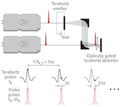
Asynchronous optical sampling (ASOPS) is an approach to ultrafast optical TDS that avoids the above issues. It was pioneered in 1987 using picosecond lasers1 and was transferred to the femtosecond world by the use of two femtosecond lasers with repetition rates fR at 1 GHz locked together in a master-slave configuration with a slight offset ΔfR.2 This offset—typically between 1 and 10 kHz—causes the delay among pairs of pulses from the lasers to incrementally increase by Δτ = ΔfR/fR2 with each shot—for example, by 10 fs at ΔfR =10 kHz.
If the lasers are then used as pump and probe lasers, time-delaying happens automatically and the delay τ between pump and probe pulse pairs undergoes a linear ramp τ = t×ΔfR/fR as function of real time t, replicating itself at a rate given by ΔfR. Figure 1 illustrates the principle for a terahertz-TDS setup. The lasers are then used exactly as in a classical setup except that no translation stage is required. Timing precision is now determined by the ability to measure and stabilize the repetition-rate offset. Uncertainties at the level of a few parts in 105 are reached—typically more than an order of magnitude better than mechanical delay generators.
The key feature of the ASOPS approach is speed, enabling applications that are impossible with mechanical delay generators. A typical system scans 1-ns-long TDS traces at sub-100-fs resolution within an acquisition time as short as 100 μs. By comparison, a translation stage would have to move a 5 cm distance at an average speed of 1500 m/s to achieve the same result. This gives the user full freedom to acquire data in a single-shot fashion in very rapid succession, or to average an arbitrary number of scans to enhance the signal-to-noise ratio. A further bonus of ASOPS is that the temporal zero point does not need to be searched—a task that can be quite tedious in a classical setup.
Three applications where ASOPS shows its advantages are wafer mapping based on transient differential reflection data, terahertz spectroscopy, and spectroscopy in transient multitesla magnetic fields.
Wafer mapping
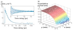
A common method for wafer metrology or monitoring the growth of multilayer nanostructures is the use of laser-induced picosecond ultrasound, where a strong laser pulse launches a heat wave (that is, very high-frequency ultrasound) into a sample, often via a metallic transducer, and the echoes returning from buried interfaces are detected via reflectivity changes at the sample surface.3 We have used this technology to map an x-ray Bragg mirror consisting of 60 silicon/molybdenum (Si/Mo) layers sputtered onto a monocrystalline Si wafer to investigate post-manufacturing growth homogeneity. The nominal layer period is 6.8 nm and the total stack thickness 408 nm. A reflectivity signature for this sample is shown in Fig. 2a. The initial peak marks the excitation pulse at time zero. The subsequent ringing is an interference signature of the multiple echoes from the intrastack interfaces and the multilayer period can be calculated from the oscillation frequency.The echo around 130 ps delay arises from the mirror-to-substrate interface, indicating the total stack thickness. We have scanned a 50 × 50 pixel area with 200 μm pixel spacing at the wafer edge-the resulting mirror period distribution is shown in Fig. 2b. A detailed analysis shows that variations at the center of the stack are below 0.1 nm, and also reveals a significant period reduction because of growth inhomogeneity towards the edge. The acquisition time required for this 2500 pixel image is around 4 h (6 s per pixel). This may seem long, but in comparison, a measurement with a translation stage would have taken around two days of total acquisition time. While 4 h may be insufficient for volume mapping applications, ASOPS could still make the difference to real-world applicability of wafer monitoring based on picosecond ultrasound. With system optimization and partial sacrifice of measurement precision, we envision that it would be relatively straightforward to reduce the single point measurement time to a few tens of milliseconds and the total image acquisition time to a few minutes. Such potential does not exist with translation stages, as these would then have to accelerate and decelerate around 1 million times per minute while maintaining an average speed of around 1–2 m/s.4
Spectroscopy in the 0.1–10 THz range of the electromagnetic spectrum is another area that relies on ultrafast optical TDS—precision and speed are key factors for applications. Terahertz spectroscopy has great potential for use in gas spectroscopy and sensing, explosives and drugs detection and monitoring, in-line paper or foil thickness measurements, solar-cell inspection, etc.5 It also has widespread application in the fundamental physical sciences.
Terahertz spectroscopy
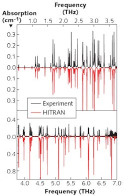
To judge the ASOPS-based system, a measured absorption spectrum of ambient air with 28% relative humidity between 0.5 and 6.5 THz and with 1 GHz resolution is compared to data compiled from the HITRAN database, a widely accepted reference for spectroscopic data.6 The total measurement time was 60 s (see Fig. 3). The qualitative agreement between the spectra, even for the smallest and weakest features, is remarkable. Differences in the absorption values are at the 1% level for frequencies below about 2.5 THz, increasing at higher frequencies only because of limitations in the dynamic range of the system, which could be overcome by a longer averaging time.An evaluation of the frequency accuracy of our data compared to the HITRAN reference shows a mean error of only 140 MHz, or 9 × 10⁻⁵ in relative units, which is in line with earlier-mentioned expectations. These values are at least an order of magnitude lower than reports for classical systems that we are aware of with comparable measurement time and bandwidth. Even at a 1 s acquisition time, the mean frequency error only slightly degrades to 160 MHz. This level of precision has been shown to enable accurate spectroscopy of weakly concentrated constituents of a gas mixture within a highly absorbing background by fitting and subtraction of reference data.7
Spectroscopy in transient magnetic fields
The final showcase is an application of terahertz TDS that is entirely impossible with classical mechanical delay generators: spectroscopy in transient magnetic fields. Such measurements are of interest, for example, for contactless determination of the electron mobility and effective mass in semiconductors via measurements of the terahertz cyclotron resonance frequency, used for research into AlGaN-based power transistors.
The required magnetic field strengths are often >10 T and are only accessible via magnets delivering pulses with duration at the 10 ms level. As the pulse is nonuniform, to acquire meaningful data a system must slice the available 10 ms measurement window under the field pulse into sufficiently small fractions while remaining able to measure a full terahertz spectrum each time.
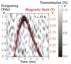
We have used an ASOPS system with an offset frequency of 7 kHz—that is, an acquisition time of 143 μs per terahertz spectrum-in such a scenario to acquire 100 traces under the pulse and resolve the evolution of the cyclotron resonance of a 2D electron gas in a GaAs/AlGaAs heterostructure as the magnetic field evolves. Figure 4 shows the evolution of the sample transmission and the measured magnetic field as function of time with a clear signature of the cyclotron resonance and correlation with the magnetic field.8 Electron mobility and effective values can directly be calculated from this measurement. This shows that ASOPS is an enabling technology for applications of ultrafast optical TDS in scenarios with rapidly varying experimental conditions or for investigations of transient phenomena. Apart from pulsed magnetic fields, other scenarios are discussed in the literature—for example, transient biological phenomena such as protein folding or spectroscopy in operating combustion motors.The experiments summarized here have been performed using two taccor lasers with 1 GHz repetition rate, along with the repetition-rate-offset-stabilization unit TL-1000-ASOPS, both from Laser Quantum. While indeed the requirement for two lasers instead of one has a cost implication, this is easily outweighed by the benefits of losing the translation stage for some applications. For those applications, the step from stage to ASOPS is probably equivalent to the step from an analog data plotter to a digital sampling oscilloscope.
REFERENCES
1. P. A. Elzinga et al., Appl. Opt., 26, 4303 (1987).
2. C. Janke et al., Opt. Lett., 30, 2357 (2005).
3. C. Thomsen et al., Phys. Rev. B, 34, 4129 (1986).
4. N. Krauss et al., Opt. Express, 23, 2145 (2015).
5. M. Tonouchi, Nature Photon., 1, 97 (2007).
6. L.S. Rothman et al., J. Quant. Spectrosc. Radiat. Transf., 110, 533 (2009).
7. G. Klatt et al., IEEE J. Sel. Top. Quantum Electron., 17, 159 (2011).
8. B.F. Spencer et al., Appl. Phys. Lett., in preparation (2016).
Albrecht Bartels is CEO of Laser Quantum GmbH, Konstanz, Germany, and Thomas Dekorsy is professor of physics at University of Konstanz, Germany; e-mail: [email protected]; www.laserquantum.com.


