Advances in Optical Systems: How to apply laser-induced damage threshold (LIDT) test techniques

JASON YAGER
Laser light has several unique properties, including monochromaticity, high coherence, and high collimation. As a result, the laser has become an essential tool for a wide variety of applications, including materials processing, communications, medical, and security and defense.
With advances in materials and optical coatings, laser optical systems can now attain beam intensities on the order of a petawatt, or 1015 W. However, since the demonstration of the first laser in 1960 by Ted Maiman,1 one of the major limitations remains optical damage. Optical components in high-energy and high-power laser systems such as lenses, mirrors, nonlinear optics, prisms, and fibers must be chosen correctly to ensure that sufficient margin is maintained to avoid laser-induced damage (LID). A correct understanding of how laser-induced damage threshold (LIDT) is measured is crucial for determining the suitability of an optic for a given application.
Fundamentals
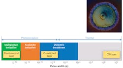
Laser-induced damage is defined according to ISO 21254 as any permanent laser-radiation-induced change in the characteristics of the surface or bulk of a specimen that can be observed by an inspection technique. LID can be categorized into two main fundamental mechanisms: thermal and field-induced (see Fig. 1).
Thermal: For continuous-wave (CW) lasers, the damage threshold is driven by thermal absorption.2 This mode of damage is often seen in long-pulse lasers as well, with pulse widths as low as ~10-8 s. The damage happens because of melting and/or vaporization of material. The absorption is greater than the material's ability to disperse the heat through thermal conductivity. The LIDT for CW lasers can be represented as power density and is referred to as the irradiance, which is equal to power per area (such as W/cm2).
Field-induced: For shorter-pulse laser sources with pulse durations on the order of 10-8 to 10-14 s, the damage threshold is driven by photoionization effects or field effects (see Fig. 1). Field effects are often discussed in terms of fluence or energy density, which is equal to energy per area (for example, J/cm2).
Photoionization is ionization produced in a medium by the action of electromagnetic radiation. The electric field couples into the medium, exciting electrons into the conduction band by absorption of photons. These electrons create a plasma that, upon reaching critical density, interacts directly with the incoming photons because of the plasma frequency resonating with the laser frequency. The plasma temperature then increases exponentially, initiating an explosive expansion and thus forming a shock wave that can appear like a spark and possibly cause an audible snap.
Heat from the plasma can couple into the surrounding lattice, causing thermal damage if the pulse duration is long enough. For pulse durations between 10-10 and 10-13 s, avalanche ionization plays a primary role. For femtosecond lasers with pulse widths <10-13 s, multiphoton ionization processes are the primary driver, and their role increases as the pulse duration decreases. This regime is the basis for cold laser processing, as the plasma expansion time is so short that the energy cannot be transferred effectively to the surrounding material.3
Laser-damage testing protocol
The most commonly used test protocols are ISO-21254, "Lasers and laser-related equipment –Test methods for laser-induced damage threshold," and its predecessor, ISO-11254. These international standards are used to determine the irreversible damage of optical components under the influence of a laser beam in such a manner that the results are reproducible and independent of the test lab.
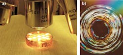
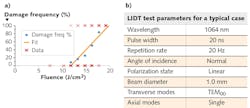
Examples include 1-on-1 tests (a single pulse per site) and S-on-1 (multiple shots per site). Damage can be defined as any permanent laser-induced change that can be observed by an inspection technique, typically 150X differential-interference-contrast (DIC) microscopy. DIC microscopy is also known as Nomarski interference-contrast microscopy (see Fig. 2). This illumination technique is used to enhance the contrast in transparent samples. DIC is based on the principle of interferometry to gain information about the optical path length of the sample, illuminating otherwise invisible features.4Laser damage test station layout
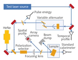
A representative exposure test arrangement is shown in Fig. 4. This test source is a flashlamp-pumped, electro-optically Q-switched, Nd:YAG oscillator-amplifier constrained to operate in a single transverse mode (TEM00).5 The output of the test source is set to the desired level with a variable attenuator, combined at a dichroic with the visible beam from a helium-neon (HeNe) laser, and delivered to the test sample located at or behind the focus of a best-form positive lens. Use of a lens permits generating destructive energy densities (fluences) at the test sample.The lens is mounted on a translation carriage that allows setting the irradiated spot size to the desired value—once set, the spot size is held constant during the test. The sample is mounted in a precision multi-axis stage, which is used to position different test sites in the beam and to set the incidence angle. The polarization state is selected with a waveplate.
The incident laser pulse is sampled with uncoated quartz wedges-portions of the beam are directed to various detectors for measurement of total pulse energy, spatial profile, and temporal waveform. The sample surface and the visible laser radiation scattered from it are observed with a 20X optical microscope (not shown in the figure).
Scaling LIDT results
Because the LIDT results are highly dependent on the test parameters used, a common question is whether the results can be mapped to other wavelengths or pulse widths. For pulse-width scaling, an industry-accepted approximation of Root T scaling can be used. The scaling coefficient is specific for a pulse-width regime. For example, "root T" scaling with scaling proportional to T1/2 (where T is pulse duration) can be used from roughly 30 ps to 100 ns as:
Irradiance (MW/cm2) = Irradianceold (MW/cm2) * SQRT(Told/Tnew)
or as:
Fluence (J/cm2) = Fluenceold (J/cm2) * SQRT(Tnew/Told)
Wavelength scaling has been shown to be inaccurate and is not recommended—see the white paper "Laser Induced Damage Threshold Wavelength Scaling, Fact or Fiction"6 for more information. A proper understanding of laser-damage thresholds can avoid costly mistakes by ensuring that an optical component will achieve the required performance for your application.
REFERENCES
1. T. H. Maiman, Nature, 187, 493–494 (Aug. 6, 1960); doi:10.1038/187493a0.
2. R. M. Wood, "Laser-induced damage by thermal effects," Laser-induced Damage in Optical Materials, 9–23 (2015).
3. G. L. Wood, "Laser induced optical damage in solids," Center for Night Vision and Electro-Optics (Jul. 1991).
4. D. B. Murphy and M. W. Davidson, Fundamentals of Light Microscopy and Electronic Imaging, 2nd ed., 173–197 (2012).
5. S. C. Sietel, Laser Damage Test Handbook and Database of Nd:YAG Laser Optics, 2.7–2.8 (1998).
6. See http://bit.ly/2c4ggxg.
Jason Yager is the general manager for laser damage testing at Quantel USA, Bozeman, MT; e-mail: [email protected]; www.quantel-laser.com.


