Laser Applications: Galvo scanners reach megahertz-scale range repetition rates for laser micromachining

The availability of ultrashort-pulse (USP; also known as ultrafast) lasers, which offer very precise machining capabilities, has resulted in expanded capabilities for laser micromachining. However, when optimizing high-throughput and high-quality laser-machining processes for use with USP lasers, new factors must be considered. First of all, the ablation efficiency—meaning the specific removal rate in terms of cubic millimeters per minute and watt—has to be maximized. In particular, to achieve good surface quality, the peak fluence has to be chosen correctly.
Increasing pulse energy and spot size
The naive approach for increasing the ablation rate in terms of volume per time would be to simply increase the average power. However, to preserve the highest machining quality, the average power has to be increased together with the laser pulse repetition rate or the ablation area to preserve the laser peak fluence at the optimum point. In addition, a good machining quality requires a pulse-to-pulse distance—the so-called pitch—that is somewhere in the range of one-half to one spot radius, or in other words, a pulse overlap of on the order of 75%. For a given pitch p and a spot radius w0, the overlap o is:
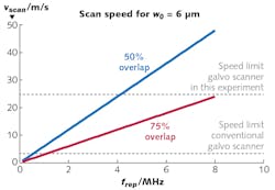
The operation range in terms of pulse repetition rates for currently available USP laser systems is in the single-digit megahertz range. As a result, very high scan speeds are required to preserve the optimum pulse overlap. Figure 1 shows the calculated scanning speeds for a spot radius w0 = 6 μm and repetition rates up to frep = 10 MHz.
Test setup and first results
The laser system used is a model Fuego from Lumentum (formerly Time-Bandwidth Products; Milpitas, CA) that generates 10 ps pulses. The light emitted from the laser passes through a λ/4 waveplate that generates circular polarization and is then guided via four mirrors to the scanner aperture. A beam expander is installed in front of the scanner.
The experiments were performed at the 532 nm second-harmonic-generation (SHG) wavelength using a focusing objective with a focal length of 100 mm, resulting in a spot radius w0 of 6.2 μm and a beam quality m2 of better than 1.1. (Both of these values were measured with a scanning-slit beam profiler.)
For testing the accuracy of the new scanner system, a polished silicon wafer was used as sample material. The scale-up of the ablation process is performed on polished stainless steel 1.4301 (or, in the U.S., AISI 304) having a threshold fluence of 0.064 J/cm2, resulting in an optimum laser peak fluence of 0.47 J/cm2. The ablation experiments were performed at this laser peak fluence.
The galvo scan system used in the experiments was SCANLAB's intelliSCANse 10. In a closed-loop digital proportional-integral-derivative (PID) control architecture, the mirror positions of the two galvanometer motors for the two scanning axes are controlled using the position information provided by optical digital encoders based on the company's patented skew-error (SE) technology. The use of digital encoders allows for better linearity of the position angle scale, which is essential for the uniformity of the distribution of laser pulses along the scanning path.
Unlike common angular position encoders relying on a disk scale attached to the end of the axis of the galvanometer scanner, the SE encoder is equipped with a small mirror that deflects a light beam. While the scanner axis is rotating, the light beam is scanned over a stationary scale. Benefiting from the low inertia and high signal quality enabled by this encoder design, the galvanometer scanners maintain dynamic performance and precision even at very high scanning speeds beyond the usual range of speeds accessible with galvanometer technology.
Typically, the parameters for the closed-loop PID position control have to be tuned to the desired dynamics of a galvanometer scanner. To avoid unstable behavior of the closed-loop PID position control, a tradeoff is made between dynamics (bandwidth) and maximum speed for the operation of the scanner.
To enable the experiments reported here, a special tuning was developed that allows for highest speed, releasing the galvanometer speed limit at the expense of tolerance on input of improper position trajectories. The trajectories for the control algorithm need to be planned carefully, avoiding accelerations beyond the dynamics of the system. Because the PID controller has a finite bandwidth, the scanner system is not free from tracking errors, which might limit the overall precision of the scanner system in the application. The performance must be measured experimentally. The trajectories were planned using the Reflexxes Motion Libraries online motion-generation software by Reflexxes (Hamdorf, Germany).
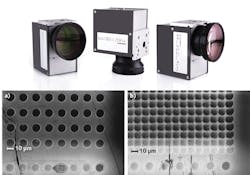
To evaluate the accuracy of the scanner system at high speeds, a reference pattern of holes is shot with the scanner at standstill. In Fig. 2, this pattern is visible as the lowest line on the picture.A scan speed of 6 m/s and a repetition rate of 285 kHz yielded a pulse spacing of 21 μm (see Fig. 2a). There is no visible deviation of the position of the holes from the holes in the reference line. In Fig. 2b, the scan speed was increased to 25 m/s and the repetition rate was set to 2.1 MHz. The resulting pulse spacing is 12.5 μm, and there is a maximum deviation of the position of the holes from the holes in the reference line of 5 μm visible.
These results show that a scan speed of 25 m/s with high accuracy can be achieved, allowing the operation of the laser in the megahertz regime.
Increasing the repetition rate
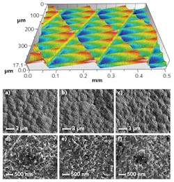
Figure 3 shows the surface and a 3D structure of a shark-skin pattern that was generated at a repetition rate of 2 MHz and a scan speed of 6 m/s. Increasing throughput means increasing the average power to get a higher ablation rate. Just increasing average power by the use of higher pulse energies leads to a bad surface quality, especially for stainless steel. Therefore, the optimum laser peak fluence is maintained by increasing the average power jointly with the laser pulse repetition rate.The experiment was performed using unidirectional and bidirectional scan modes. The achieved specific removal rate (the removed material per time and average power) is not influenced by the used scan mode. The surface quality is still good for the highest-used laser repetition rate of 8.2 MHz. Only a small increase of melting "worms" and droplets can be observed, and there are no differences between the two scan modes. These results lead to the conclusion that the ablation process using the mentioned setup and parameters can be scaled up to the megahertz regime without any negative influence.
New scan control algorithms
While the methods applied in the experiments show a dramatic increase in productivity as compared to standard galvo-scanner-based systems, to some extent the benefit arrives at the expense of flexibility. Only rectangular processing areas have been realized up to now—for different geometries to be processed, the parameters have to be carefully tuned to achieve satisfying accuracy, and complex programming limits the usability. Furthermore, the required forerun length to stabilize the scanner speed limits the duty cycle, especially for short lines (small structures).
To address these shortcomings, further experiments are planned in which an excelliSCAN scan head equipped with the SCANahead control platform will be used. This technology relies on a zero-tracking-error control algorithm implemented directly in the scanner-control electronics.
Within a 1 ms preview time window, the positioning commands received by the scanner controls are automatically preprocessed and executed without the effects of a tracking error. The control algorithm is optimized to access the full acceleration potential of the galvo scanning axes at any scanning speed, enabling much faster settling times for the stabilization of scanner speed and, as a result, higher throughput. The built-in automatic control functions and revised precise position feedback at high speed will allow the programming of more-complex processing tasks, such as nonrectangular shapes and smaller structures.
Using infrared light rather than a 532 nm wavelength will enlarge the spot size and thus the ablation area. Therefore, machining with higher average power will result in full use of the power provided by today's USP lasers. Marking with galvo scanners can be optimized in relation to the machining time by choosing the proper scan velocity for a given marking distance. Together with this optimum scan velocity, a maximum duty cycle is observed, which is 50% for bidirectional scanning. The forerun length needed to stabilize the scanner speed limits the duty cycle, so using a new control algorithm that deals with this problem will result in higher throughput. Other strategies to overcome this limitation, such as distributing the laser pulses to multiple galvo heads, must be kept in mind as well.
Holger Schlüter | Head of Business Development, SCANLAB GmbH
Dr. Holger Schlüter is Head of Business Development at SCANLAB GmbH (Puchheim, Germany).
Beat Jaeggi
Beat Jaeggi is with the Bern University of Applied Sciences (Burgdorf, Switzerland).
Beat Neuenschwander
Beat Neuenschwander is at the Bern University of Applied Sciences (Burgdorf, Switzerland).
Markus Zimmermann
Markus Zimmermann is at the Bern University of Applied Sciences (Burgdorf, Switzerland).


