Optical Coherence Tomography: OCT measures industrially applied car paint to characterize metal flakes
Many cars are coated with paint that exhibits a metallic or glittery sheen—the properties of the sheen are determined by the distribution and characteristics of metal or mica flakes used in the paint. Most modern cars are coated with four paint layers—electro-coat, primer coat, base coat, and clear coat—with the base coat containing the flakes. Confronted with many painting parameters such as type of spray nozzle, spray speed and pattern, air pressure, and distance of the nozzle from the surface to be painted, the automotive engineer needs to be able to experimentally characterize the orientations and depths of flakes in a base-coat layer to fine-tune the coating process.
Now, a measurement approach based on optical coherence tomography (OCT) can provide the automotive industry with a practical way to automatically analyze these metal flakes, which until now have been difficult to image.1
The size, weight, and geometry of the flakes, as well as the viscosity of the paint, influence the flake orientation. The automotive industry currently uses ultrasound imaging to examine car paint in quality-assurance (QA) checks. Although ultrasound instruments are easy to use, they cannot effectively image the metal flakes used in many modern car paints. Ultrasound measurements also require equipment to be in contact with the sample, which means ultrasound cannot be used for in-line monitoring without interfering with the paint job.
The new approach, developed at the University of Liverpool (Liverpool, England), uses a time-domain full-field (FF) OCT system for noncontact characterization of metal flakes in paint, including their size (which on average is around 10 μm in diameter and 1 μm thick), number, and orientation.
"The painting step is a bottleneck in the manufacturing process," says Yaochun Shen, lead researcher on the project and professor at the University of Liverpool. "If the finished car paint does not meet requirements, then it must be removed chemically and the car completely repainted. This not only costs time and money, but also creates chemical waste and associated environmental issues."
High-resolution OCT plus algorithm
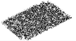
To image the flakes, the researchers designed a 3D FF-OCT instrument with very high lateral spatial resolution to distinguish minuscule flakes and a high depth resolution to see the position and orientation of each one. Because a single 3D OCT image contains thousands of flakes (too many to be measured manually), the researchers also developed an algorithm to automatically identify and describe each flake in a sample (see figure).
In the system, light from an infrared LED with a center wavelength of 850 nm and bandwidth of 80 nm is split to form the interferometer that is at the heart of the device. Fringes occurring because of interference between light from the sample and reference arms (as long as the path difference is within the coherence length of the light source) appear on the OCT system's CMOS image detector, which operates at a 100 frames/s imaging rate.
The acquisition and data-processing procedure include data acquisition by the FF-OCT system; convolution process, Hilbert transform, and base-coat isolation; 3D segmentation and labeling; and determination of the flakes' properties such as size, number, and orientation.
Tests of the technique on five automotive paint samples (two silver, one blue, and two black) showed that the OCT system worked well for imaging the top two layers of car paint, which includes the base layer with the metal flakes. Using it with the 3D analysis algorithms allowed the researchers to determine the number, size, and orientation of metallic flakes within the paint samples with, for example, the mean flake density (number of flakes per square millimeter) ranging from 202 to 533, depending on the type of paint.
Although the researchers demonstrated their approach on samples of applied car paint, they say that with further development the technique could be used for in-line monitoring, where it could detect problems that occur during the painting process.
REFERENCE
1. J. Zhang et al., Opt. Express (2017); doi:10.1364/oe.25.018614.

John Wallace | Senior Technical Editor (1998-2022)
John Wallace was with Laser Focus World for nearly 25 years, retiring in late June 2022. He obtained a bachelor's degree in mechanical engineering and physics at Rutgers University and a master's in optical engineering at the University of Rochester. Before becoming an editor, John worked as an engineer at RCA, Exxon, Eastman Kodak, and GCA Corporation.
