Laser Optics: Selecting the right aspheres for laser applications
Aspheric elements enhance performance in many optical designs. Complex aspheric surface profiles can greatly reduce or eliminate many aberrations in spherical-lens optical systems, improving performance, reducing weight, decreasing assembly time, and diminishing tolerance stack-up. Not all aspheric lenses, however, are created equal, especially when being integrated into a laser system.
The manufacturing technique you select to fabricate a lens can greatly alter the performance and reliability of the laser system. The key parameters of the laser, including its energy and wavelength, can drive the choice of fabrication method for the aspheric lens.
CNC-polished aspheric lenses
The oldest technique for producing aspheric lenses is to polish them. Polished aspheric lenses are ground and polished on a single spindle using computer numerically controlled (CNC) machining. The lens spins at a high speed while a small contact area grinding tool is translated from the edge of the lens to the center. Precision control over the location of the tool allows the aspheric shape to be ground into the surface. The lens is then smoothed to a specular finish with a polishing tool.
If necessary, further correction can be accomplished with magnetorheological finishing (MRF), which works very similarly to small tool grinding, except the tool is a ribbon of fluid that changes viscosity when a magnetic field is introduced. This allows for very fine control of material removal over a small area.
Because polishing has small setup and tooling charges, costs are driven primarily by the time it takes to make each lens. Each lens is made one at a time so there is very little economy of scale for large quantities. However, the lead time for manufacturing an aspheric lens in this manner is short because there is little special tooling and setup involved in the production run. Proof-of-concept, prototype, and production lenses are all produced in identical fashions, eliminating headaches with first article runs and correlation studies between mold performance and lens performance.
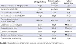
For laser system designers, the most important advantage of CNC-polished aspheric lenses is in the wide variety of materials that can be produced with this method. In fact, the choice of substrate materials is almost limitless and includes all common glasses on the Abbe Diagram; UV transmitting materials such as fused silica and calcium fluoride; and infrared (IR)-transmitting materials like germanium, zinc selenide, and chalcogenide glasses. Thus, the aspheric lenses can be designed to withstand the high energies associated with modern laser systems. The Table gives some of the common characteristics available with the different aspheric lens manufacturing techniques.
Precision glass molding
Precision glass molding (PGM) has been the dominant manufacturing technology for laser diode collimation since the inception of the technology in the early 1980s. The ability to mass-produce a single-element glass lens with aspheric surfaces at low cost presents an ideal combination for optical designers and system engineers. The use of aspheric surfaces enables optical designers to optimize designs to a single element and obtain superior performance to spherical designs, while the molding process enables thousands of lenses to be replicated with excellent resolution at very low cost. Single-element, aspheric precision-glass-molded lenses have been the preferred choice for the majority of laser diode collimation applications, from CD/DVD players and industrial tools to medical devices.
The precision glass molding process is typically an isothermal compression molding process. The process starts with a glass preform, which is inserted between a set of molds in a precision glass molding machine. These molds replicate the desired surface on the finished lens and are compensated for the thermal molding profile and glass and tooling properties. The molding machine is purged with nitrogen and the preform and tooling heated. Pressure is then applied and then the mold is allowed to cool, resulting in a finished lens.1
While precision glass molding offers immense economies-of-scale in volume production, it does have a few disadvantages as well. First, this method has high initial costs because of the cost of manufacturing the mold accurately from a very durable material, while accommodating for the glass shrinkage. Accommodating for the glass shrinkage typically introduces a long lead time because several iterations are involved to correct the tool shape. However, once the mold is manufactured, many lenses can be made quickly on the tooling, with little expense for upkeep of the tooling. Also, continuous improvements in the modeling of glass shrinkage is reducing the compensation time and expense for the tools, which reduces both the cost and lead time of the molds.
The other disadvantage of this method is in regards to material choices. Because molding is a thermal process, only materials with relatively low transformation temperatures (Tg) can be used. The transformation temperature of a glass is the temperature at which glass transforms from a lower-temperature glassy state to a higher-temperature cooled-liquid state. The higher the Tg, the higher the cost of a finished molded lens because of the energy and time required to first heat and then cool the glass.
The glass map for moldable materials is ever-expanding and contains glasses with indices from ~1.4 to ~2.0, but generally lacks UV transmitting materials. Also, since damage from a laser can be thermally induced, very careful consideration needs to be given to using molded lenses with high-power laser sources.
Hybrid aspherizing
Hybrid aspherizing technology (considered hybrid because the lenses produced have both glass and polymer surfaces) starts with the creation of a spherical glass lens that then becomes aspherized through the addition of a molded polymer surface. The polymer is solidified in the mold by curing with UV light. This is done at room temperature with little pressure, so the mold tool does not need to be as durable as a glass mold tool.
Because the technique is done at room temperature, little to no thermal shrinkage is involved and the shape of the mold does not need to deviate from the shape of the final lens. The lead time and cost of tooling is higher than polishing an aspheric lens, though significantly lower than glass molding.
The unit cost of hybrid aspherized lenses in medium and higher volumes is low, but there are several limitations that need to be considered before using them in a design. The polymer is not as durable as glass, so it is not recommended that the hybrid asphere be applied to an external surface of a multi-element design, unless there is some means of protecting it from the outside environment.
There are also limitations on the thickness and uniformity of the surface. When designing a surface, the thickness should be maintained between 50 and 200 µm across the entire aperture of the lens, so mild departures from the base spherical shape are required. This means that hybrids are best used for mild aberration correction, rather than large spherical corrections typically seen in large-aperture fast aspheric designs. However, because the polymer surface can be applied to any surface in an optical design, its benefits can easily be combined with other aberration-correcting optics in an optical train.
One common use is to add the aspherized surface as the final surface in an achromatic lens—freeing the doublet from spherical correction, and yielding better color correction and spherical correction than a doublet or triplet would achieve without the aspherized surface.
As with precision glass molding, material selection is an issue with hybrid aspherizing. Research is ongoing to create resins that transmit in the UV or IR spectra, but today the polymer surface is limited to visible and near-IR (NIR) transmission. And as the surface is a polymer, it is susceptible to thermally induced laser damage.
Producing a specific beam profile
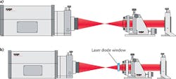
Optical designers usually include an aspheric lens into their laser systems to get as much of the light into as small a spot as possible. Ensuring this is fairly easy with any of the above techniques, as the lens can be monitored and inspected for wavefront error. The wavefront error specification is determined during the optical design phase, and validation of the design and specification is done when first prototypes are produced and measured. Measurement of the root mean square (RMS) wavefront error is typically done on an interferometer in a dual-pass configuration (see Fig. 1a).Most visible wavelength interferometers use HeNe lasers operating at 632.8 nm, but most lenses are not designed to be used at that wavelength. To account for this difference between the design and test wavelengths, the optical performance is modeled at 632.8 nm and used to establish appropriate specifications for in-process quality assurance.
Many lenses are designed for use with specific laser diodes, and laser diodes typically have a protective window through which the laser light travels as it is emitted. In these cases, the lens design will include the thickness and refractive index of that window, and the test configuration for the lens will include a representative window in the optical path (see Fig. 1b).
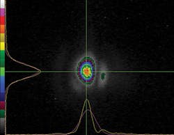
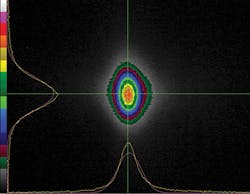
Wavefront error specification is used for many applications because it is sufficient and cost-effective. However, for more demanding applications, particularly non-focusing applications, this measurement method is often not sufficient since it does not provide useful information regarding the intensity profile of the resulting laser beam. For applications where this is critical, a commercially available camera and accompanying software are typically used. Additional effort, and therefore cost, is required in the manufacture of the molds to ensure the lens meets these more demanding requirements.It's important to work with your lens manufacturer during the design of a laser optical system. If the lens manufacturer knows the wavelength of the laser, the power of the laser as it impinges on the optical surfaces, and the resulting goal of the laser system, they will be able to manufacture a lens that meets your needs.
Likewise, understanding the budgetary constraints and long-term forecast of the product being developed can help determine a starting solution for manufacturing process. Standard aspheric lenses, produced by each of the three techniques described, are available for proof of concept, prototyping, or integrating directly into a laser system.
REFERENCE
1. A. Symmons, Molded Optics: Design and Manufacture, ch. 5, CRC Press, Taylor and Francis Group, London (2011).
Gregg Fales | Senior Product Line Manager, Edmund Optics
Gregg Fales is senior product line manager, both at Edmund Optics (Barrington, NJ).
Alan Symmons | Executive VP of Operations, LightPath Technologies
Alan Symmons is executive VP of operations at LightPath Technologies (Orlando, FL).
William Moreshead | Manufacturing Engineering Manager, LightPath Technologies
William Moreshead, Ph.D., is manufacturing engineering manager at LightPath Technologies (Orlando, FL).
