Photonic Frontiers: Optical Design Software: Looking Back/Looking Forward: The growing power of software drives photonic innovation
Optical design is computationally intensive. A century ago, human computers traced rays with pencil, paper, and books of log tables. Mechanical calculators came after World War I. Digital computers came after World War II, and soon helped design powerful optics for surveillance planes and satellites.
Today's optical design software is based on the same principles of ray tracing, but makes design much easier. The software optimizes designs in a series of iterations, using criteria specified by the designer, with success depending on the designer's skill. Software has also gone far beyond designing lenses and mirrors to simulations of a wide variety of optical systems and devices, including lasers and nonlinear optics.
Digital computers
The first step toward automation was mechanically pushing keys on electromechanical calculators, proposed by Eastman Kodak in 1940. The system finally built in the early 1950s sped up ray tracing, Rudolf Kingslake said in a 1987 interview, but the mechanical fingers "beat the insides out of the Fridens".1 In 1945, Herbert R. J. Grosch used punch-card accounting equipment for ray tracing while working for IBM at the Watson Research Institute of Columbia University.2
James G. Baker used the first relay-based programmable computer, the 1944-vintage Harvard Mark I, to trace rays, but it took 120 s to trace one ray through one surface. The Harvard Mark IV, delivered in 1952, needed about 1 s per surface. Baker tried to automate design with iterative calculations, but did not realize his calculation method converged too slowly to be useful.3
The first stored-program computer in the country, the Standards Eastern Automatic Computer delivered in 1950 to the National Bureau of Standards (Gaithersburg, MD), traced rays a thousand times faster than the Mark I. But it was tied up with classified military projects until 1953.
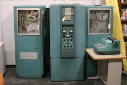
In 1953, Robert Hopkins at the University of Rochester began ray tracing and calculating third-order aberrations on an IBM card program computer. In 1956, Kodak switched to a Bendix G15 computer, a 950-lb. machine the size of a tall file cabinet that could trace about one ray-surface a second with its 450 vacuum tubes and 300 germanium diodes (see Fig. 1). Others followed: In 1962, Hopkins wrote "Today practically all geometrical optical design is being done on digital computers."4 He expected large computers to soon replace small ones such as the G15.
The Fortran era
By the mid-1960s, software was written in FORTRAN and batch-processed on decks of punched cards. By the time of the 1966 "Lens Design with Large Computers" conference in Rochester, computers had been accepted as a powerful tool for skilled designers. By 1970, early versions of current design software such as ACCOS V and CODE V had been developed. But with batch processing, designers had to wait hours for results of each run.
The 1970s brought the age of interactivity, initially with terminals attached to a mainframe and later with programmable desktop machines. Doug Sinclair at the University of Rochester started working on an HP-65 programmable pocket calculator, and later turned to the more powerful HP-9845 programmable desktop. Although lacking the power of a mainframe, they gave users quick results. Sinclair left the university in 1975 to form Sinclair Optics (Rochester, NY), which developed and marketed OSLO for optical design on those machines and later personal computers.
The design environment evolved along with computing. The timeline lists work environments since the mid-1970s, as recalled by Kevin Thompson, R&D group director at the Optical Solutions group of Synopsys (Pasadena, CA).
User-friendly design
Laser Focus World increased our computer and software coverage during the 1980s, and by 1990, we were running a monthly column on optics and information software.
Our November 1990 issue listed 12 major lens-design software packages, with their origins in different eras. Of those that identified the programming language, three were written at least partly in FORTRAN, hearkening back to mainframes: ACCOS V from Harris Scientific Calculations, Code V from Optical Research Associates (now the optics division of Synopsys (Pasadena, CA), and SYNOPSYS from Optical Systems Design (Boothbay Harbor, ME). GENII-PLUS from Genessee Optics, OptiCAD from Opticomp Corp., OSLO, and parts of SYNOPSYS were written in C, a language first developed for minicomputers. SODA from Don Small Optics was written in Basic, primarily a PC language. Most were available for more than one operating system for workstations or PCs.The need for user-friendly PC interfaces was stressed in the December 1990 issue by Michael Kidger of Kidger Optics (Crowborough, East Sussex, England). Ease of use had not been important with minicomputers because few nonspecialists could afford them. PCs were affordable, but user-hostile software discouraged nonspecialists from trying to design optics on them. Kidger was quick to embrace the Macintosh interface, and in late 1985 introduced a Mac version of its SIGMA optical design software, incorporating the pull-down menu interface we now consider standard.
The trend spread through the industry. In our May 1995 issue, Optical Research Associates advertised a new graphical interface for its Code V software as an alternative to its programmable command language.
Growing software variety
A 24-page software section in our October 1995 issue highlighted the growing variety of software, including types going well beyond the traditional ray-tracing models.
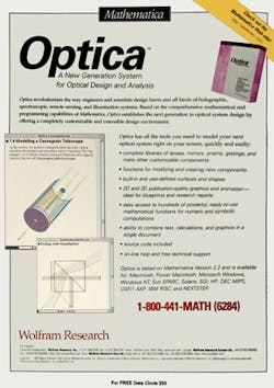
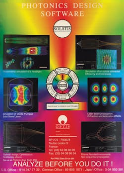
One new trend was optical design in general-purpose computing environments. Wolfram Research (Champaign, IL) advertised Optica, an optical design and analysis system based on its Mathematica computer algebra program (see Fig. 2); MathWorks (Natick, MA) advertised the imaging processing capabilities of its MATLAB computing environment; and RayCAD (Tyngsboro, MA) advertised its AutoRay optical design and ray tracing program based on AutoCAD.Focus Software (Tucson, AZ) advertised its ZEMAX optical design program, but other new players offered other types of software. Breault Research Organization (Tucson, AZ) advertised ASAP for optical system analysis; Optiwave (Ste.-Foy, QC, Canada) advertised BPM_CAD to model and design optical waveguides; and OPTIS (Toulon, France) advertised SOLSTIS, which included laser beam propagation analysis (see Fig. 3).
In an article, Scott Weller of Optikwerk (Rochester, NY) described a database manager to track the optical design process, to be added to a new version of its Optikwerk design software. He said it would help designers share vital information with manufacturing engineers.
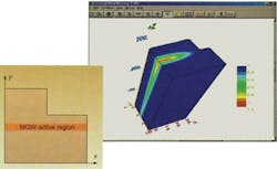
Modeling and simulation software, long used in laser research, also went commercial. In our January 2000 issue, J. Simon Li described simulation software from Crosslight Software (Vancouver, BC, Canada). The goal was to model effects such as temperature sensitivity of laser threshold that could lead to nonlinear effects and saturation of laser power to aid design optimization (see Fig. 4). "Now anyone with a modest background in laser physics can apply commercial simulators to real-world problem solving and device optimization." Li wrote.Lighting, illumination, and computer imaging
Ray tracing has found growing applications beyond imaging systems. For "non-imaging" optics used in illumination, ray tracing must consider scattered light as well as reflection and refraction, says Ed Freniere, president of Lambda Research (Littleton, MA). Monte Carlo models determine the probability of scattering in various directions.
In our May 2005 issue, R. John Koshel of Lambda Research described how ray tracing and visualization techniques could model the appearance of illuminated objects, an important consideration in lighting design.
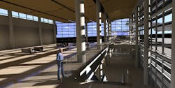
In our October 2010 issue, Ian Ashdown of byHeart Consulting (West Vancouver, BC, Canada) showed how ray tracing systems can make computer-generated images look realistic. Figure 5 renders complex interior lighting effects in a glass-wall building. "The next generation of lighting design software will become the common tool of both lighting designers and architects," showing both daylight and artificial lighting effects.Continuing refinements and more options
There's no standing still in design software. The basic model for analyzing thin-film coatings "has remained virtually unchanged for more than 60 years," wrote Angus Macleod of the Thin Film Center (Tucson, AZ) in our July 2013 issue. But that model assumes ideal conditions—in the real world, illumination is neither perfectly monochromatic nor perfectly collimated, and coatings are not ideal uniform layers. He showed how refinements in the Essential Macleod software can calculate these effects.
In a July 2014 review of lens design software, we noted that some companies offered software to design both imaging and nonimaging systems. Synopsys offers LightTools for nonimaging applications, which can swap files with its CODE V application for imaging systems. Lambda Research offers TracePro for both imaging and nonimaging design, as well as a much-enhanced version of OSLO for imaging. Radiant Zemax (Redmond, WA) built illumination-system as well as imaging design into its OpticStudio software.
Photon Engineering (Tucson, AZ) includes both imaging and illumination design in its FRED Optical Engineering System. In a May 2015 review of biomedical optical design, Rich Pfisterer of Photon Engineering said FRED could serve as a virtual prototyping tool for optical hardware. "FRED makes it possible to simulate the hardware in software rapidly and accurately, and so it is a cost-effective tool for many biomedical applications developers."
More software options
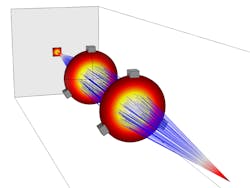
Our December 2014 issue reported that COMSOL (Burlington, MA) had added a ray optics module to its Multiphysics software suite. That complemented other modules that solve electromagnetic wave equations on scales of a few wavelengths, but can't practically model propagation over large numbers of wavelengths. "The Geometrical Optics interface is useful for modeling large structures in which waves can propagate in many directions while undergoing reflection and refraction at boundaries," wrote Christopher Boucher, a COMSOL software developer. That allows modeling of complex processes, such as thermal effects shifting the focal point of a lens when it transmits a 3 kW laser beam (see Fig. 6).In our February 2015 issue, Karl Beeson, Mary Potasek, and Evgueni Parilov of Simphotek (Newark, NJ) tell how simulation software can help users match lasers to their application requirements. By solving rate equations for two-photon scanning spectrometry, their SimphoSOFT simulation software can compare how well different lasers excite fluorescing dyes and proteins. For one such application, they found that fixed-wavelength femtosecond fiber lasers could have about the same number of photons and image quality as more costly tunable Ti:sapphire lasers.
In our August 2015 issue, Manyalibo Matthews of the Lawrence Livermore National Laboratory (Livermore, CA) described a COMSOL simulation of optical damage with powerful pulses from Livermore's National Ignition Facility. The NIF optical flux approaches the damage threshold, so simulation helps reduce the chance of damage, and can aid in repair and recycling of any damaged optics.
Figure 7 simulates a key process in optical damage, mass transfer along the surface of laser-heated glass arising from gradients of surface tension. By studying that model, Livermore found that pulses lasting tens of microseconds could heat the glass just enough to evaporate surface material without causing the tiny fractures from nanosecond or shorter pulses. The Livermore group hopes to extend their technique to selective laser melting for 3D printing.
Looking forward
Optical design software has evolved to meet changing needs. Cell-phone cameras were a new idea 20 years ago. "Nowadays most cameras in the world are in cell phones," says Freniere. The lenses must be tiny to fit into phones, and they must focus light onto tiny imaging arrays, requiring much higher performance than older lenses needed to focus onto 35 mm film. Advances in manufacturing allow production of exotic surfaces that perform well.
New software can optimize designs, but it takes expertise to get the best results, says Freniere. Designers need to know the right starting point for optimization models and how to strike the best balance among performance, cost, manufacturability, and such constraints as the tight size limits on cell-phone cameras.
The LED illumination revolution poses new challenges for non-imaging optical design. Mistakes are apparent in the harsh glare from some LED street lights, which put small, intense emitting areas in the field of view of drivers and pedestrians.
The photonics world is still exploring the capabilities of general-purpose software like COMSOL Multiphysics. Its ability to model many parameters in an array of unit cells lets it simulate the impact of factors such as thermal expansion, mechanical strength, and optical gain simultaneously, and process large volumes of data.
Complex software faces its own challenges. Input data as well as modeling techniques must be assessed carefully. Computer scientists coined the phrase "garbage in, garbage out" before Laser Focus World was born, and that issue remains. But good software has become essential to modern lasers and photonics, and we will need even better software to take full advantage of such emerging technologies as optical metamaterials and integrated photonics.
REFERENCES
1. J. Hecht, "Optical design enters the computer age", Comput. Phys., 1, 1, 34–41 (Nov/Dec 1987).
2. H. R. J. Grosch, J. Opt. Soc. Am., 35, 803A (1945).
3. D. Feder, Appl. Opt., 2 ,1209 (Dec. 1963).
4. R. E. Hopkins, J. Opt. Soc. Am., 52, 11, 1218 (Nov. 1962).

Jeff Hecht | Contributing Editor
Jeff Hecht is a regular contributing editor to Laser Focus World and has been covering the laser industry for 35 years. A prolific book author, Jeff's published works include “Understanding Fiber Optics,” “Understanding Lasers,” “The Laser Guidebook,” and “Beam Weapons: The Next Arms Race.” He also has written books on the histories of lasers and fiber optics, including “City of Light: The Story of Fiber Optics,” and “Beam: The Race to Make the Laser.” Find out more at jeffhecht.com.
