The higher quantum efficiency of electron-multiplying CCDs leads to higher performance expectations compared to intensified CCDs, but they appear to perform better only at light levels above those that require cooling or slow scan.
A charge-coupled device (CCD) is an array of photodiodes (light-sensitive pixels) that are electrically biased so that they generate and store electrons (electric charge) when illuminated with light. The amount of charge trapped beneath each pixel directly relates to the number of photons illuminating the pixel. This charge is then "read out" by changing the electrical bias of an adjacent pixel so that the charge travels out of the sensor, is converted into a voltage, and is then digitized into a numerical value. This action is performed for each pixel to create an electric image of the scene. Electronics inside the camera control the read-out process.
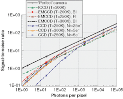
FIGURE 1. Based on a plot of S/N variation against signal (φ pτ) for ICCD and EMCCD systems at 20-ms integration time, there is no significant improvement of the S/N when cooling the sensor of an ICCD system. The upper black line represents the ideal case of a shot noise–limited imaging system with a QE of 100%. In this plot the ICCD camera is assumed to have a filmless gallium arsenide phosphide image intensifier with a peak quantum efficiency of 50%, an electron gain, G, of 500, a noise factor, F, of 1.6 and a read-out noise, N r, of 25e– at 250K and 300K. EMCCD cameras with both front-illuminated (FI; QE = 50%) and back-illuminated (BI; QE = 90%) CCD sensors are shown. We chose an on-chip multiplication gain of 500, a noise factor of 1.4, and a read-out noise of 25e– at 300K, 250K, and 200K and a charge-transfer noise of 5.4e–.
In an intensified camera (ICCD), an image intensifier is placed in front of the CCD chip to enhance its light-detection capability. These photon multipliers typically comprise three main components: a photocathode, a microchannel plate (MCP), and a phosphor screen. The photocathode converts the incident photons into electrons, which are then multiplied to a number dependent on the gain voltage (typically 600 to 900 V) applied to the MCP, and finally converted by the phosphor screen back into photons ready for the CCD to detect. The phosphor screen is usually coupled to the CCD by a fiberoptic bundle. Some manufacturers use high-numerical-aperture coupling lenses, which provide superior distortion-free image quality compared to taper-coupled systems.
The electron-multiplying CCD (EMCCD) camera is an alternative approach that does not use a standard image intensifier. Instead, an electron-multiplying structure (called a gain register) is inserted between the end of the shift register and the output amplifier. The design of this gain register is such that its high voltage causes impact ionization that generates new electrons. Consequently, this technique enables charge (photon-induced but also unwanted thermally generated charge) from each pixel to be multiplied on the sensor before it is read out.
Because of these different processes, ICCD and EMCCD systems behave differently in terms of resolution, speed, sensitivity, and noise. Noise characteristics are probably the most important criteria when comparing imaging systems because they determine the detection limit. Here, we address the theoretically calculated signal-to-noise ratio (S/N) characteristics of ICCD and EMCCD cameras.
Noise sources
Several noise sources limit the performance of scientific-grade ICCD and EMCCD cameras. Potential noise sources in such systems include the signal-inherent shot noise, dark current, and read-out noise that is generated in the detector.1
Shot noise. Shot noise is a fundamental property of the quantum nature of light and arises from statistical fluctuations in the number of photons emitted from an object. This noise source is unavoidable and always present in imaging systems. In terms of signal-to-noise ratio the best a detector can do is to approach the shot-noise limit. The pseudo signal produced by shot noise (Nshot) can be described by Poisson statistics:
[1]
where G is the overall electron gain; η is the quantum efficiency (QE) that characterizes the photoelectrons generation process at a given wavelength; φp is the mean incident photon flux in photons per second per pixel; τ [s] is the integration time in seconds; and F is a noise factor that quantifies the noise introduced by the gain process itself. For an ICCD or EMCCD system, F is gain dependent and falls within the range 1.3 < F < 2.2
Dark current. Dark current is caused by thermally generated electrons in the silicon substrate of the CCD. The dark current is often incorrectly confused with its noise, but because the constant pattern signal part is repeatable, this can be subtracted from image data. If not subtracted, it does add its own typically noisy looking contribution to the image, but almost all of this disappears when a dark-field subtraction is performed.
Superimposed on this signal is statistical modulation in the form of shot noise—the same as in the photon signal we want to measure. In any CCD system, dark-current noise (Ndc) is given by the square root of the dark-current signal.
In the particular case of EMCCD cameras, note that any dark current still remaining will be multiplied up along with the signal. Hence, when calculating the signal-to-noise ratio, the dark-current noise must be multiplied by the on-chip multiplication gain of the EMCCD—which is why EMCCD chips ideally must be well cooled (down to -73°C), thus drastically increasing the cost of such a device.
Read-out noise. Read-out noise (Nr) is generated by the electronic circuitry that converts the charge from each pixel into a digitized light-intensity proportional number that is displayed in the image. When the accumulated charges are shifted on the CCD chip, electrons can be left behind or jump ahead. Read-out noise is always present and also includes "reset noise," output amplifier noise, and quantization noise. It is frame-rate and temperature dependent but independent of integration time. Typical numbers are given later in this article.
For EMCCD detectors, any noise generated by the charge-transfer process across the sensor area before reaching the gain register would be multiplied. We included this effect in our analysis as charge-transfer noise (CTN) Nct. We define read-out noise in EMCCDs as:
[2]
where Nro represents all other nonmultiplied read-out noises.
Total noise. For "white noise" the mean-square fluctuations do add, so the overall noise generated by ICCD or EMCCD cameras is then given by:
[3]
Signal-to-noise ratio
We compare the S/N performances of ICCD and EMCCD cameras by first calculating the S/N obtained within a single frame in a quasi-video mode and then its increase through frame adding or extended integration time.
Single-frame operation. The signal-to-noise ratio for a single frame is given by:
[4]
The S/N varies as a function of the number of photons per pixel (fpt) for cooled and uncooled ICCD and EMCCD cameras as shown in Fig. 1. This analysis shows no significant improvement of the S/N when cooling the sensor of an ICCD system.3 Indeed, we observed that, beyond an electron gain of roughly 100, the ICCD at room temperature operates in the shot noise–limited mode. Hence, we consider chip cooling of an ICCD camera as being unnecessary and a useless cost increase of the system.
For EMCCD detectors, any CCD noise (dark current and charge transfer) is multiplied up along with the input signal and can lead to very poor S/N especially in low-light situations. Shot noise–limited operation can only be achieved by applying strong cooling to reduce the dark current and very slow pixel rates to minimize the impact of charge-transfer noise. In that case, because of its 1.8 times higher quantum efficiency, the S/N provided by the back-illuminated EMCCD technology is expected to be up to 50% higher than for ICCDs.
Long frame integration vs. frame adding. The S/N generated by a single frame can be increased under constant illumination by taking longer frames or adding successive short frames (see Equation 4).
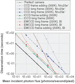
With the same operational parameters used in the previous section we find that EMCCD cameras must be deep-cooled and operate with long integration times to perform comparably to ICCDs. In the case of ICCDs, uncooled frame adding and cooled long-term integration result in very similar behavior. Again, there is no sensor cooling needed in the case of short frame times. Slow-scan ICCDs would need cooling because of their long readout times (see Fig. 2). However, this would not result in any better performance.
Applications of ICCD and EMCCD cameras
Despite the expectation for performance improvements fed by their high QE, EMCCD systems do not seem to be superior to ICCD at low light levels. They provide better S/N only at light levels that would not require cooling or slow scan.
The EMCCD cameras seem to be a credible alternative to ICCDs for some applications, but their theoretical capabilities must not be overestimated because, in practice, charge-transfer noise greatly reduces their noise performances in low-light situations even at low frame rates. They cannot compete when it comes to gate times faster than a few milliseconds.
Comparison images taken under very similar conditions and quantum efficiencies show that the ICCD camera seems to perform better not only when fast gating is required, but also in general low-light-level applications (see Fig. 3).
REFERENCES
- M. O'Malley and E. O'Mongain, Optical Engineering 31(3), 522 (March 1992).
- D. J. Denvir and E. Conroy, Proc. SPIE 4796, 167 (July 2002).
- D. Dussault and P. Hoess, Proc. SPIE 5563, (August 2004; In print).
Authors' note
Excel spread sheets for all calculations are available from the author via e-mail.
DAVID DUSSAULT is an application engineer at Paul Hoess (Munich, Germany) and PAUL HOESS is president of Stanford Computer Optics (Berkeley, CA) and general partner of Paul Hoess KG; e-mail: [email protected].


