ANTONY ORTH
We tend to think of optical fibers as powerful tools for transmitting time-varying optical signals for telecommunications. While this is their most common application, optical fibers have found niche applications outside the traditional telecom arena. One of these applications is in biomedical imaging—specifically for endomicroscopy.1 Here, microscale resolution is used to assess potentially pathological tissues in vivo without having to harvest the tissue, as is done in a traditional biopsy.
Optical fibers are ideally suited for imaging deep into the body at high resolution, where scattering makes standoff imaging impractical. Owing to their small size, optical fibers can be inserted directly into regions such as the lungs or the gastrointestinal tract.2, 3 Since optical fibers are thin, tissue damage can be minimal, and typical wavelengths of operation in the visible and infrared are non-ionizing.
Despite these features, one fundamental physical problem stands out for fiber-optic imaging: how to transmit an optical image through an optical fiber. Optical fibers scramble spatial information. If one attempts to relay a spatially and temporally coherent image (from a laser) through an optical fiber, the output will be a speckle pattern.4 This is a result of a wide variety of physical phenomena inside the fiber, from modal coupling to geometrical and material imperfections in the fiber.
Recently, a number of research groups have demonstrated that these speckle patterns can be decoded and the original image recovered with sufficient pre-calibration.5, 6 Unfortunately, these approaches require that the fiber remain nearly static during operation, which is at odds with the requirements in a dynamic clinical setting where the fiber needs to bend and twist into hard-to-reach regions of the body.
These so-called wavefront shaping and transmission matrix approaches are also only applicable to coherent light. Even worse, an incoherent image—such as that from fluorescence illumination—is output as an indistinct blur and immune to wavefront or transmission matrix recovery techniques. This is particularly unfortunate, as fluorescence is an extremely valuable and high-contrast imaging modality.
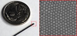
Luckily, there is a decades-old solution to this problem: optical fiber bundles.7 Each bundle is a collection of thousands of very small optical fibers, with each fiber effectively transmitting one pixel of an image (see Fig. 1).
Fiber bundles are typically used in “contact mode” for imaging, where the bare fiber facet is put in direct contact with the sample. This obviates the need for a lens and helps keep the sample in focus by providing built-in force feedback to the clinician. Typically, the fiber bundle cores are surrounded by a common cladding and separated by 10 µm or less. Crosstalk between cores is relatively low over lengths of interest to biomedical imaging (around 1 to 3 m), so the fidelity of the image is maintained along the fiber.
Because light-collection efficiency is always a concern in imaging applications, the core-cladding contrast is relatively high to maintain a high numerical aperture. Consequently, the cores themselves are multimoded. This last observation is quite valuable, though it is often overlooked—the cores transmit more information than a simple intensity measurement.
Hidden information
Consider a plane wave of light impinging on the input facet of an optical fiber. It is well known that the coupling efficiency of the plane wave to a given fiber mode is highly dependent on the incoming angle of the plane wave with respect to the fiber axis. A high input angle generally increases coupling efficiency to higher-order modes, while the fundamental mode is most efficiently coupled to on-axis modes.8
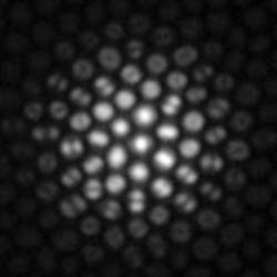
The presence of higher-order modes indicates that the original incoming light arrived at a large angle (see Fig. 2). Therefore, by quantifying high- vs. low-order modes coming out of each core in a fiber bundle, one can deduce the distribution of input angle of the incoming light.9 This fact has important implications for imaging.One typically thinks of an image as a spatial distribution of light. In the ray optics picture, the light rays also have an “angular” distribution—that is, they arrive at the image plane at a wide variety of orientations and the image of an in-focus point object may contain the full range of angles admitted by the numerical aperture within one pixel. With increasing defocus, the central pixel will contain a smaller distribution of ray angles, centered around a ray that is normal to the fiber facet. This is apparent in Figure 2, where the central core appears as a single spot (fundamental mode), whereas the peripheral cores carry a variety of spatial patterns such as dual lobes and rings. In this way, the distribution of ray angles tells us about the focus of the object. Put another way, this angular distribution yields depth information.
The light field
The collection of spatial and angular light ray information from an imaging fiber bundle is called “the light field.”10 This quantity has four dimensions—two spatial and two angular—that encode the embedded 3D structure of a scene. With the light field in hand, one can perform a variety of digital-optical manipulations in post-processing. For instance, the original focal plane can be adjusted by modifying the spatioangular coordinates of the recorded light rays. One can also change the viewing perspective, generate stereo views, and quantify depth.
Numerous light field imaging devices have been developed over the last few decades, both in academia and commercially. The most common design uses a lenslet array at the image plane of a camera, with the image sensor placed one (lenslet) focal length behind the lenslet array. The camera sensor essentially images the Fourier planes of the small sections of the image sampled by each lenslet in the array. Other possible geometries include camera arrays and angle-sensitive pixels. But a recent paper demonstrates that fiber optics provides yet another light field sensing architecture.11
Fiber-optic light field sensing
Using the relationship between mode profile and angular ray distribution, one can extract a light field directly from the sample and can then be can visualized in 3D (see Fig. 3). For endomicroscopy, advantages of the fiber-optic light field sensing approach are numerous.The first and most obvious advantage is size. An optical fiber bundle is about 0.5 to 1 mm in diameter. Engineering a robust micromechanical system with focusing capabilities at that scale is a considerable challenge for alternative imaging methods. Bulk-optic probes with moving parts are also more difficult to clean and are more expensive than bare fiber, leading to higher clinical procedure costs.
Ease of use is another advantage. With a traditional imaging system that images a single focus plane, the sample is not always in focus throughout the measurement scan. In fact, maintaining focus at a microscopic scale inside the body using a single-fiber probe is not an easy task, leading to blurry frames with unusable data. Light field data, on the other hand, can be refocused to an extent, which helps to recapture otherwise out-of-focus images.
3D stereo imaging outlook
Light field imaging using bare optical fiber bundles was recently demonstrated this year, while a previous paper introduced the concept of using the modal profile as a proxy to the angular distribution of light rays.9,1 While the approach is an incoherent technique, it has thus far been demonstrated in fluorescence, as this gives optimal signal-to-noise ratio owing to the large contrast of fluorescent agents.
With this concept verified in the lab, the next step is to determine promising use cases in the clinic. As demonstrated, light field fiber-bundle imaging is a microscopy technique, and not a route to macroscopic light field imaging due to the small physical size of the entrance aperture (the fiber bundle facet diameter). Therefore, appropriate use cases are those where abnormal cellular structure and organization indicate a potential pathology.
The path to market for medical devices also involves regulatory approval. Fortunately, the fiber-optic bundle light field imaging approach piggybacks off clinically established fiber bundles. The physical probe that enters the patient is unchanged from already approved devices, which should ease the regulatory burden. There may also be appropriate applications beyond biomedical imaging, such as remote industrial inspection where medical regulations are not an issue.
REFERENCES
1. B. A. Flusberg et al., Nat. Methods, 2, 12, 941–950 (2005).
2. L. Thiberville et al., Eur. Respir. J., 33, 974–985 (2009).
3. R. Kiesslich et al., Nat. Rev. Gastroenterol. Hepatol., 8, 10, 547–553 (2011).
4. Y. Choi et al., Phys. Rev. Lett., 109, 203901 (2012).
5. M. Plöschner, T. Tyc, and T. Čižmár, Nat. Photonics, 9, 8, 529–535 (2015).
6. A. M. Caravaca-Aguirre and R. Piestun, Opt. Express, 25, 3, 1656–1665 (2017).
7. A. F. Gmitro and D. Aziz, Opt. Lett., 18, 8, 565–567 (1993).
8. A. W. Snyder and J. Love, Optical Waveguide Theory, Springer Science & Business Media, New York, NY (2012).
9. A. Orth et al., Opt. Express, 26, 5, 6407–6419 (2018).
10. M. Levoy et al., ACM Trans Graph., 25, 924–934 (2006).
11. A. Orth et al., Sci. Adv., 5, 4, eaav1555 (2019).
Antony Orth is a research officer at the National Research Council of Canada, Ottawa, ON, Canada; e-mail: [email protected].


