TERAHERTZ OPTICS: How to choose the best terahertz or infrared bandpass filter for your application
WILLIAM R. McGOVERN
Terahertz and infrared (IR) bandpass filters are used for restricting a broadband source or reducing out-of-band light to the detector. Spectrometer system performance is affected by factors such as temperature of operation, the type of filter used, application use, and physical phenomena that cause the filtering behavior. In addition, not all bandpass filters can survive harsh environments. This analysis can help determine which terahertz or IR filter technology to select for a particular application.
Bandpass filters (BPFs) allow out-of-band radiation to be rejected before reaching the detector. Once stray or out-of-band radiation is eliminated, signal-to-noise ratio increases in most cases. Use of a BPF does attenuate the in-band signal; however, certain BPF designs exhibit mission-acceptable in-band transmission greater than 95%.
Filter applications
Bandpass filters improve detection sensitivity of small IR and terahertz peaks by a broadband detector (thermal IR) by preventing ultraviolet (UV) or visible radiation (as well as longer wavelengths) from reaching the detector. Applications vary from improving astronomical imaging of the Crab Nebula at 24 µm and 70 µm1 and near-IR (NIR) night-vision applications typically up to 10 µm, to reducing out-of-band transmission for free-electron lasers2, serving as frequency calibration standards for IR and terahertz instruments, and use as transmissive substrates to observe spectral enhancement of self-assembled monolayers.3 In addition, BPFs are used to shield avionics and guidance systems from electromagnetic interference (EMI) and radio-frequency interference (RFI) in military applications.4
Use of the terahertz range in particular is growing due to defense and sensing applications developed after the September 11 terrorist attacks. Research on terahertz use in nondestructive tests, military and civilian security, chemistry, medicine, and biology applications has grown significantly. In addition, there is an increasing demand for greater computing and communications bandwidths that will eventually require “terahertz” (300 GHz to more than 3 THz) frequencies.
In other research, three of NASA’s IR astronomy programs—SAFIR, CLARREO, and SOFIA—seek to better understand changes in Earth’s climate, with discoveries powered by a wide range of IR filters. As a result, BPFs have become critical hardware built into astronomy and instrument applications for these spectral regions.
Advantages and disadvantages of different far-infrared and terahertz bandpass filter technologies
| Filter type | Advantages | Disadvantages |
| Absorption | Sharp cut-on wavelength for short-wavelength side; commercially available | Limited transmission range; doping and material choice defines spectral window |
| Cross-absent Metal-mesh self-supported | High transmission (to 95% T); good for mid-IR, THz, and far-IR applications; can cool to 4 K; thin design; stackable for better rejection and sharper cut-on if needed | Limited full-width half-maximum (FWHM); cut-on more gradual than dielectric interference filter |
| Dielectric interference filter | Sharp cut-on and cut-off; several suppliers for visible and near-IR wavelengths | Only for visible, near-IR, and limited mid-IR applications; can delaminate with cold or heat; filter becomes millimeters thick at mid-IR |
| Polymer supported multilayer patterned filter | Sharp cut-on; customizable center wavelength; custom FHWM and patterns; thin design | Not readily available commercially off-the-shelf |
Bandpass filter types
There are several types of BPF technologies currently available for terahertz and far-IR applications (see table).
Absorption-type filters include filters made with materials like germanium (Ge), zinc selenide (ZnSe), and 5-mm-thick n-type silicon (Si).5 Quartz has a shorter wavelength window that extends from 150 nm to 3.5 µm.5 Silicon, Ge, and ZnSe can be used to filter out visible and NIR radiation, while allowing midwave-IR (MWIR) wavelengths longer than 1 µm to pass (depending on material and thickness). Lattice (phonon) absorption bands form the long-wavelength edge of the bandpass filter for Ge, ZnSe and 5-mm-thick n-type Si.5
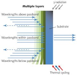
Multilayer dielectric interference filters are made by chemical vapor deposition (CVD). Stacks of different materials with different indices of refraction are deposited on a substrate in a vacuum chamber. These types of filters are used at shorter IR wavelengths, but typically are not used in the mid- or far-IR. Since their required thickness increases as wavelength increases, they can become highly cost prohibitive or difficult to manufacture at far-IR wavelengths.6 In addition, in the mid- to far-IR spectral range, multilayer thin-film dielectric filters can delaminate under the stress of cryogenic temperature cycling7, making them inappropriate for some applications (see Fig. 1).
Polymer-supported multilayer patterned filters are a promising BPF technology. Because the filters are polymer supported, concentric shapes and designs are possible, making them ideal for longpass, shortpass, and bandpass applications. Optical modeling software is typically necessary for these designs to be successful, as light interacts with multiple layers of patterned metal and polymer. This type of filter offers great design flexibility with respect to band edges, bandwidth, and rejection levels; however, most are custom made and not off-the-shelf products.
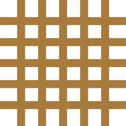
For metal-mesh filters, “metal mesh” is a nonspecific term for a frequency selective surface (FSS). Metal-mesh filters come in several build geometries for shortpass and bandpass filters, depending on the type of FSS that they use. Metal-mesh filter designs are typically self-supported structures with a wire grid or a patterned metal material with shapes removed (such as crosses, circles, fans, and slots).
Cross-absent metal mesh filters are used to selectively filter far-IR radiation before it reaches the detector, providing a more environment-tolerant and versatile option. These types of filters have been used in far-IR and submillimeter research for more than fifty years, and provide numerous benefits.8-9 They can improve detection capabilities by blocking out-of-band interferences and allowing transmission of only the desired spectral regions. They can also transform a cheaper detector with a broader detection profile into a high-performance detector. Filtering can improve signal-to-noise ratio (SNR) of a detector by eliminating out-of-band radiation from reaching the detector and causing spurious signal or saturation of the analog-to-digital converter.
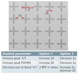
Much of the geometric area is closed and mirror-like with a design that is primarily reflective to out-of-band radiation. In Lake Shore models such as this, a thin, cross-absent, gold mesh foil is held flat and in place by an outer support ring. A Gaussian profile high-transmission IR spectrum results from the cross-absent metal-mesh geometry (see Fig. 3).The pitch or repeating period of the crosses is defined as g; the gap between adjacent crosses is known as 2a; the width of one cross arm is known as 2b; and the resonant wavelength of the bandpass filter is equal to λ = 2g - 4a - 2b, as long as the length of the crosses are smaller than the resonant wavelength or center wavelength (CWL).9 Each of these parameters in the cross pattern geometry affect BPF performance.
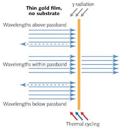
The cross-absent BPF design uses the interaction between meshed circuits and the traveling electromagnetic (EM) wave.6 For radiation that is adjacent to the passband, EM waves interact with the BPF metal and generate resonating electrons at the edges of the holes, producing interference effects that block out-of-band frequencies.10 The center band frequencies propagate through the BPF without generating resonating electrons10 to give high transmission within the CWL of the BPF (see Fig. 4).Optical simulations show that thickness of the free-standing metal layer has a minor effect on BPF performance. The metal thickness should be greater than the calculated skin depth for the material used (aluminum, silver, gold, or copper) at the resonant frequency (CWL), but further increases in thickness lead to slightly decreased in-band transmission.
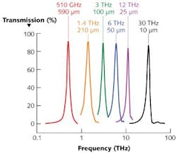
In-band transmission of cross-absent BPFs up to 95% has been observed (see Fig. 5). The bandwidth remains relatively constant as the center passband frequency changes, typically between 7 and 25% full-width half maximum (FWHM).Out-of-band transmission (high frequency side) for the BPF studied is typically below 4.6% (Fig. 5). If BPFs are chosen with the same center frequency band, out-of-band transmission (high-frequency side) for two BPFs in series can be as low as 0.3%. Other research groups report incoherent stacking of four similar BPFs to achieve 50 dB stopband rejection.6
Harsh environments
Since they have no heavy substrates and no vibronic bands due to polymer support layers, free-standing metal-mesh BPFs are lightweight. Other designs typically use a polyethylene or polypropylene polymer support layers composed of hydrocarbon (-C-C-H) molecular chain structures. As light passes through these substances, the -C-C-H structures produce their own absorbance spectrum that can interfere with desired spectroscopy or astronomy bands. In addition, most polymer materials have poor radiation tolerance that leads to mechanical instability of the filter.
As free-standing structures held in nickel support rings, the metal-mesh BPF filters are less than 2 mm thick for easy insertion into tight spaces and standard filter wheels. They also have a low thermal mass compared to other filters to reduce heat load, cooling down to cryogenic operating temperatures.
A single-layer gold-foil BPF displays no adverse optical effects in the presence of radiation. In laboratory tests, free-standing BPFs have been exposed to more than 300 krad (Si) ionizing gamma radiation from cesium 137 without differences in Fourier transform infrared (FTIR) spectra. In contrast, CVD-deposited multilayer interference filters typically have limited radiation tolerance, especially at noncryogenic temperatures, and can suffer from radiation darkening and damage in these environments.
Cross-absent BPFs also stand up well under vibration. After a free-standing BPF was continuously vibrated at a frequency of 440 Hz for 13 weeks, there was only a small 1.7% transmission difference observed in the before and after FTIR spectra.
Most critically, cross-absent BPFs are cryogenically stable (down to 4 K) and vacuum compatible. Separate laboratory show that BPFs perform well when cycled in a probe station under vacuum and cooled with a closed-cycle refrigerator using compressed helium. One BPF was fully operational after 905 temperature cycles from room temperature (295 K) down to 55 K with only a 1% decrease in passband transmission.
For many far-IR and terahertz applications, vacuum-compatible, radiation-hard, vibration-tolerant and cryogenically stable cross-absent metal-mesh BPFs offer the best solution when comparing performance, tolerance of rugged environmental conditions, and commercial availability.
REFERENCES
1. T. Temim et al., The Astronomical Journal, 132, 1610–1623 (2006).
2. T.J. Orzechowski et al., Phys. Rev. Lett., 57, 17, 2172–2175 (1986).
3. K.R. Rodriguez et al., J. Chem. Phys., 121, 18, 8671–8675 (2004).
4. Optical Filters USA web site, “EMI/RFI Shielding” page; http://opticalfiltersusa.com/emi-rfi-shielding.html.
5. Tydex web site, “Plane windows and wedged windows” page; http://www.tydexoptics.com/en/products/spectroscopy/plane_and_wedged_windows/.
6. S. Sako et al., “Developing Metal Mesh Filters for Mid-Infrared Astronomy of 25 to 40 micron,” Proc. SPIE, 7018, 701853-1–701853-10 (2008).
7. A.T. Tokunaga, “Specifications for Astronomical Infrared Filters” (Sept. 10, 2001); http://www.ifa.hawaii.edu/~tokunaga/filterSpecs.html.
8. R. Ulrich, Infrared Phys., 7, 1, 37–55 (1967).
9. K.D. Moller et al., Appl. Opt., 35, 31, 6210–6215 (1996).
10. B. Hooberman, “Everything You Ever Wanted to Know About Frequency-Selective Surfaces, but were Afraid to Ask” (May 2005); http://calvin.phys.columbia.edu/group_web/filter_development/download/filter.pdf.
William R. McGovern is senior scientist at Lake Shore Cryotronics, 575 McCorkle Blvd., Westerville, OH, 43082; e-mail: [email protected]; www.lakeshore.com.
