GEARY SCHWEMMER, DAVID MILLER, THOMAS WILKERSON, DAVID GUERRA, and RICHARD RALLISON
When incorporated into future spaceborne platforms, light-detection-and-ranging (lidar) remote-sensing instruments will measure atmospheric and surface parameters that include topographic altimetry and atmospheric profiles of wind, humidity, temperature, trace molecules, aerosols, and clouds. It is highly desirable to have wide measurement swaths for rapid coverage rather than just the narrow ribbon of data that is obtained with a nadir-only observation. For most applications, global coverage is highly desirable, and for wind measurements scanning or pointing is required to retrieve the full three-dimensional wind vector from multiple line-of-sight Doppler measurements.
Conventional lidar receivers make up a substantial portion of the instrument's size and weight. Wide-angle scanning typically requires a large scanning mirror in front of the receiver telescope, or pointing the entire telescope and aft optics assembly. Either of these methods entails the use of large bearings, motors, gearing and their associated electronics. Spaceborne instruments also need reaction wheels to counter the torque applied to the spacecraft by these motions. Simplified conical scanning telescopes developed by scientists at NASA will use holographic optical elements (HOEs) as primaries. These HOEs will reduce the size, mass, angular momentum, and cost of spaceborne scanning lidar systems.
HOEs are easy to spin
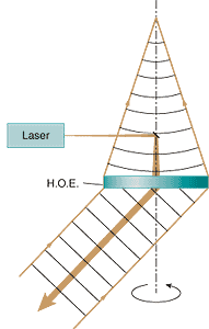
An HOE is simply a hologram of a point source that has lens-like imaging properties. Interference fringes are typically registered in the medium as variations in index of refraction, or in the case of surface holograms, as a surface-relief pattern. In a lidar application, an HOE can be used both as the transmitter collimating optic and the receiver collector. The transmitted laser beam is directed through a diverging lens with its virtual focus coincident with the focus of the HOE (see Fig. 1). The lens and HOE form a beam-expanding telescope for directing the laser beam out to the atmosphere. Atmospheric backscattered laser light acts as the collimated reconstruction beam and is focused by the HOE.The HOE is designed to diffract light at the lidar's laser wavelength to a focus located on an axis centered on and normal to the optic. By spinning the HOE in its own plane about the optic axis, the laser beam and the receiver field of view sweep out a cone. The size and mass of the rotating components is much smaller than in conventional scanning systems.
Lidar based on HOEs
Two operating lidar systems based on scanning HOE technology have been developed at NASA. The first such system, called the Prototype Holographic Atmospheric Scanner for Environmental Remote Sensing (PHASERS), was a joint development between NASA Goddard Space Flight Center (GSFC; Greenbelt, MD) and the University of Maryland (College Park, MD). The system has undergone several transformations since seeing first light in 1995 in a collaborative effort between GSFC and St. Anselm College (Manchester, NH), but continues to be based on a reflection HOE for use at the doubled Nd:YAG laser wavelength of 532 nm.
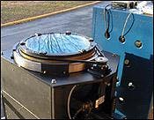
The next step was to develop infrared transmission HOEs for use with the Nd:YAG fundamental in the Holographic Airborne Rotating Lidar Instrument Experiment (HARLIE; see Fig. 2). The HOE spins like a compact disk in a large ring ball bearing and belt driven by a small motor. In an aircraft, the HOE faces down, looking out through a window at an angle of 45° off nadir. The window is 15 cm larger than the 40-cm diameter HOE to accommodate the off-axis look angle. The HOE focal length is 1 m and produces a spot 160 μm in diameter, diffracting 85% of the incident light.HARLIE is an operational, field-deployable lidar that measures aerosol, cloud, and boundary-layer backscatter for atmospheric research. It has flown several times and is also used from a ground-based trailer in an upward-looking mode. The HOE generates a 45° conical scan pattern by rotating at speeds up to 30 rpm. Like PHASERS, the HOE in HARLIE serves both as the laser collimating lens as well as the receiver-telescope primary optic. The telescope is coupled to the receiver package via optical fiber. The transmitter is a diode-pumped Nd:YAG laser operating at 1064 nm, delivering 1-mJ pulses at a 5-KHz repetition rate. The receiver has a 200-μrad field of view and a 0.5-nm optical bandpass. The photon-counting data system uses a single Geiger-mode silicon avalanche-photodiode detector. The scan controller can be used in point-and-stare, eight-position step-stare, and continuous-scan modes of operation.
Data-visualization challenges
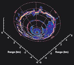
The backscatter data obtained from a stationary (that is, ground-based) scanning HOE lidar is on the surface of a cone. When the data is viewed over many consecutive scans, motion on this surface is revealed over time as the atmosphere advects over the site. In a moving platform such as an airplane or satellite, the data from consecutive scans cover different areas under the flight path, revealing atmospheric structure in three dimensions (see photo at top of this page).
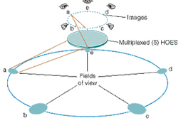
The newest concept in holographic scanning lidar receivers is one in which the scanning is accomplished by optically addressing multiple holograms in a sequential fashion without moving the HOE, called the Shared Aperture Multiplexed Holographic Telescope (SAMHOT). Several HOEs can be embedded in the same holographic film using multiple exposures in a manner such that each will act on a different set of light rays corresponding to a specific wavelength and angle of incidence (see Fig. 3). Provided there is sufficient angular separation between the planes of diffraction of the HOEs, there will be minimal impact of each on the performance of the others. All of the multiplexed HOEs will share the same full physical aperture for the collection of light rays.While the conically scanned holographic telescope technology has reduced scanning-lidar receiver size and weight by approximately a factor of three, SAMHOT technology will reduce it by another factor of three to four by eliminating the major moving parts and the motor, power supply, and encoder devices associated with them. In addition, by developing moderately wide-field-of-view HOEs and multiplexing several of them into a single film, we will effectively create a very wide-field spectral-imaging capability.
Selecting individual HOEs
To select one HOE of a multiple-exposure hologram, the incidence angle of light must be changed with respect to the film. When using a SAMHOT to provide the final collimation and beam steering of a transmitted laser beam, this means that the laser beam must come from a different direction for each HOE. Such an operation can be done using several technologies designed for steering laser beams while they are small in diameter (a few millimeters or less). These include acousto-optic scanners that, while they require no moving parts, are typically very lossy, diffracting only several percent of the light in the desired direction. Small galvanometer-driven mirror scanners are compact and efficient, but require mechanical motion and may be more prone to failure during long-term use.
Using multiple laser heads, while more costly, will provide a level of redundancy and added life expectancy. This approach is already being used in the current generation of nonscanning space-borne lidar systems to increase the life expectancy of the instrument. Perhaps microelectromechanical systems technology will offer an eloquent solution for steering the laser beam into the SHADOE (Shared Aperture Diffractive Optical Element) .
When receiving the backscattered laser light with a SAMHOT, the particular HOE that acts on the light is predetermined by the direction of the outgoing laser beam. If all the HOES have their focal spots in the same location, however, the detector will be looking at all fields of view at once. This configuration may work in applications in which the background light level is low compared to the backscattered laser signal, but usually the opposite is the case. In addition, if a SAMHOT using a common focus is used to transmit the laser beam, the light will be divided among the multiple HOES and be directed into all fields of view simultaneously.
Therefore, the preferred embodiment of the SAMHOT will have a separate focal-plane aperture, or field stop, for each field of view. This could require multiple-focal-plane optics and detector packages, again providing redundancy in the system. But scanning mechanisms similar to those of the transmitter could also be used to convey the light from each field stop to a single detector in consecutive time intervals. In some instances, the scanning mechanism can be one and the same, with rapid switching taking place between the transmitter and the detector looking through any given field stop between the time the laser pulse is emitted and the return signal begins to arrive.
The time required is a few milliseconds for spaceborne systems, but only a few microseconds for airborne and terrestrial systems. We are currently working on developing techniques to use this technology in the ultraviolet to use with the third harmonic of Nd:YAG and in scaling the size of the HOEs to 1-m and larger diameters.
Geary Schwemmer and David Miller are scientists at NASA Goddard Space Flight Center, Greenbelt Rd., Greenbelt, MD 20771; email: geary.schwemmer@gsfc.nasa.gov. Thomas Wilkerson is a research professor at Utah State University, Logan, UT 84322; David Guerra is chair of the Department of Physics and Cooperative Engineering at St. Anselm College, 100 St. Anselm Dr., Manchester, NH 03102; and Richard Rallison is president of Ralcon Development Lab, 8501 S. 400 W. Paradise, UT 84328.


