Optical Test & Measurement: Airborne test systems study and mitigate aero-optical effects

STANISLAV GORDEYEV, R. MARK RENNIE, and ERIC J. JUMPER
Airborne lasers are useful as designators and communication links as well as directed-energy offensive and defensive weapons. All of these applications depend on good beam quality to maintain the laser's high intensity in the far field. However, the ability to focus the energy in the far field is degraded as the laser propagates through variable-index-of-refraction air.
In the atmosphere, these index-of-refraction variations are caused by temperature fluctuations along propagation paths that may be up to hundreds of kilometers in length but are usually relatively easy to correct using adaptive optics (AO). On the other hand, the index-of-refraction variations within the first few meters of propagation from the aircraft are because of "compressibility" effects, and are far more damaging to the beam and harder to correct than the atmospheric aberrations.1,2
These near-aircraft aberrations are referred to as aero-optical effects. Notre Dame's study arose from a simple question asked in the early 1990s: what is the spatial and temporal character of aero-optic aberrations? To answer this question, Professor Jumper and Ron Hugo, his graduate student, developed the first truly high-bandwidth wavefront sensor—the Small-Aperture Beam Technique (SABT) sensor.3
The SABT sensor is a Hartmann derivative sensor that makes use of a sparse array of small laser beams and analog position-sensing devices to reconstruct a time series of wavefronts by trading time and position. The use of a sparse array and the trade of time and position exploit the discovery by Mike Malley that aberrations created by passage through turbulence convect with the turbulence.
After using the SABT sensor to make the first-ever time-resolved measurements of the aberrations on an otherwise-collimated laser propagated through a Mach 0.8 shear layer, the true magnitude of the aberrations was discovered.4,5 Wavefront distortions are often quantified as the root-mean-square of their optical path difference, OPDrms. In turn, OPDrms can be used to estimate the reduction in intensity by the aberrated laser, I, from that of a diffraction-limited beam, Io, using the large-aperture approximation:For a 20 cm laser beam of wavelength λ, OPDrms was found to be >0.4 µm. For modern solid-state lasers with wavelengths around 1 µm, this yields <0.2% the intensity of a diffraction-limited beam.
Because these aberrations cause such profound implications for airborne targeting and communications systems, Notre Dame's efforts gained national attention and support, leading to the formation of the University of Notre Dame Aero-Optics Group in the late 1990s. Since then, the Group has focused on developing wavefront sensors and optical methods of measuring the aberrations imposed on laser beams, their implications, and mitigation. Research has been aided by a custom-designed, large-scale wind tunnel and the development of the Airborne Aero-Optics Laboratory (AAOL).6
Airborne beam propagation testing
The most common way to direct a laser beam from an aircraft in the early 2000s was through hemispherical turrets. Wind-tunnel studies show that this type of beam director creates complex flow patterns in its aft field of regard and shocks over the aperture at high subsonic Mach numbers, ultimately imposing serious optical aberrations on the laser beam.7
With funding from the U.S. High-Energy Laser Joint Technology Office (HEL-JTO), the AAOL Program studied subsonic optical aberrations first for two Cessna Citation Bravo aircraft and, next, migrated to Falcon 10 aircraft for a follow-on study of shock-related aero-optical effects at transonic Mach 0.8 speeds in the AAOL-T Program.8
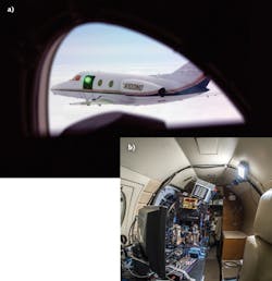
The objective of both the AAOL and the AAOL-T programs is to obtain detailed aero-optical data in flight using a source aircraft flying in formation with a laboratory aircraft. As such, the approach to both programs is similar: a laser beam leaves the source aircraft as a small, few-millimeter diverging beam that expands to overfill the turret pupil aperture on the laboratory aircraft turret. The typical formation flight distance from exiting source beam to a laboratory's turret pupil is 50 m to minimize atmosphere-related optical distortions.
The aircraft separation and relative angular position is continuously measured throughout the flight using a differential GPS system with accuracy <2 mm. Varied configurations of side-mounted turrets protrude into the slip stream of the aircraft through a highly modified door just aft of the cockpit. In flight tests, the turret is mounted to an optical bench inside the aircraft, where various types of instruments measure the turbulence-induced aberrations on the beam (see Fig. 1).
In-flight data has greatly impacted research on methods of mitigating deleterious aero-optical effects through flow control and new architectures for AO systems. Only a handful of experimental aero-optical data, collected in tunnels, was available before AAOL. The data collected on more than 15 flight campaigns so far (representing hundreds of azimuth and elevation data points each campaign) have revolutionized the understanding, treatment, and mitigation of aero-optical aberrations throughout the government, industrial, and academic communities.9
Hemisphere and ball turrets are also the geometry of choice for many airborne imaging systems. Unfortunately, aero-optical effects from the turbulent air flow around the turret cause image blurring that negatively affects the performance of airborne imaging systems.
Simultaneous measurements of the instantaneous wavefronts using the AAOL-T laboratory confirm that the turbulent wake formed by the turret imposes spatially and temporally evolving optical distortions. During recent campaigns, a target board was placed around the divergent laser beam of the source aircraft and images of the board, blurred by the turbulent wake, were recorded by a second high-speed camera on board the laboratory aircraft (see Fig. 2).Both cameras shared the same optical path to guarantee a one-to-one relation between the wavefronts and the blurred images. Relative position of both aircraft was varied to study wavefronts and resulting images in different regions of the turbulent wake. The computed spatial and temporal wavefront statistics' aberration coherence lengths and instantaneous and average OPDrms were used to compute theoretical modulation transfer functions and were compared to those obtained from the images under realistic engagement conditions. These comparisons are being used to develop new, more realistic acquisition and tracking models.10
Beyond fixed-wing aberrations
Notre Dame's research is not limited to fixed-wing aircraft. In fact, one of the more challenging projects that the Aero-Optics Group has undertaken is the experimental measurement of the aero-optical environment of a helicopter in flight. In this case, flow-induced optical aberrations arise primarily from the tip vortices of the helicopter rotor blades. The high flow speeds at the centers of the vortex cores produce strong density variations and, hence, index-of-refraction variations via the Gladstone-Dale relationship.
In the fall of 2011, the Group was offered the opportunity to make optical measurements on a full-scale helicopter in hover at the Navy's China Lake test facility. In a laboratory setting and even on the AAOL, aero-optical measurements are typically made by projecting a laser beam through the flow of interest and directing it to a Shack-Hartmann wavefront sensor. However, this technique was unsuitable for the helicopter test flight because of the inability to reconfigure the line aircraft into an AAOL-like laboratory.
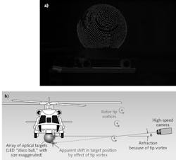
Faced with the limitations, the Group opted to use a target-imaging approach similar to the Background-Oriented Schlieren technique.11 In this approach, a target background is imaged through the optically aberrating flow. The time-varying, apparent shifts of individual points in the background are then recorded and used to back out the optical effect of the intervening flow.
Based on our previous studies, we estimated that the helicopter tip vortices during the flight test would produce a maximum local optical deflection of only 15 µrad. However, given the distance between the tip vortices and a target mounted under the helicopter fuselage, we determined that even this small deflection would produce a background distortion that could be measured using a high-speed camera within experimental uncertainty.
To accomplish this measurement, an optical target was constructed consisting of 3000 light-emitting diodes (LEDs) mounted on a 16 inch spherical globe simulating a turret. This target globe, affectionately called the "disco ball," was mounted under the helicopter at a location envisioned for a laser turret and provided more than adequate diode intensities for the high-speed, microsecond-exposure-time camera imaging at various orientations of the helicopter (see Fig. 3).Successful flight-test results from March 2012 showed that rotor tip vortices are indeed the primary source of beam aberrations, posing aperiodic, non-trivial distortions as they pass through a laser projected from that position, momentarily dropping their intensity by as much as 80% of diffraction-limited intensity and introducing jitter on the beam.12 In addition to comparing well to theoretical results, the measurements provided additional information on the strength and frequency content of the rotor-vortex aero-optical effect that will be useful for future modeling and beam-control studies by the Aero-Optics Group.
REFERENCES
1. S. Gordeyev and E. J. Jumper, Annu. Rev. Fluid Mech., 49, 1, 419–441 (2017).
2. M. Wang et al., Annu. Rev. Fluid Mech., 44, 1, 299–321 (2012).
3. E. J. Jumper and R. J. Hugo, AIAA J., 33, 11, 2151–2157 (Nov. 1995).
4. E. J. Fitzgerald and E. J. Jumper, AIAA J., 40, 2, 265–267 (Feb. 2002).
5. E. J. Jumper et al., AIAA J., 35, 4, 671–677 (Apr. 1997).
6. E. J. Jumper et al., Opt. Eng., 52, 7, 071408 (Jul. 2013).
7. S. Gordeyev and E. Jumper, Prog. Aerosp. Sci., 46, 388–400 (2010).
8. E. J. Jumper et al., 53rd AIAA Aerospace Sciences Meeting, paper AIAA-2015-0675, Kissimmee, FL (Jan. 9, 2015).
9. Special Section on Aero-Optics and Adaptive Optics for Aero-Optics, J. Opt. Eng., 52, 7 (Jul. 2013).
10. N. DeLucca et al., "Image blurring due to turbulent wakes for airborne systems: Flight tests," SPIE Optical Engineering Applications, San Diego, CA (Aug. 6-10, 2017).
11. S. B. Dalziel et al., Exp. Fluids, 28, 4, 322–335 (2000).
12. A. M. Nightingale et al., AIAA J., 54, 9, 2782–2790 (2016).
Stanislav Gordeyev is associate professor, R. Mark Rennie is research associate professor, and Eric J. Jumper is Roth Gibson professor and director, all in the Aero-Optics Group at the University of Notre Dame, Notre Dame, IN; e-mail: [email protected]; http://aero-optics.nd.edu.


