Fiber-Optic Sensing: Leveraging three decades of fiber Bragg grating sensing technology
ALAN D. KERSEY
The fiber-optic sensing (FOS) market is growing rapidly because of key advantages such as environmental robustness, electrical immunity, small size, and distributed/multiplexing capabilities. Compared to fiber sensors based on interferometric, intensity, and colorimetric techniques developed in the 1970s and early 1980s, fiber Bragg grating (FBG) sensors were latecomers to the FOS landscape. The first fiber Bragg gratings were inscribed by Ken Hill and his group in the late 1970s—in part a serendipitous discovery, as the gratings were formed because of longitudinal optical resonances from spurious end-face reflections in fiber leads feeding argon-ion light to an experimental system, which manifested themselves as lossy fibers.1
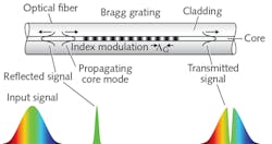
While fortuitous, this early work provided great insights on the physics of grating writing and the potential for the technology in communications and sensing. However, it was not until the development of the ultraviolet (UV) side-writing process by United Technologies Research Center (UTRC; East Hartford, CT)—which enabled spatially compact FBG fabrication—that the game changed for FBG-based optical sensing.2 Now, gratings could be distributed along a single fiber, and written at any predetermined spacing to operate over any wavelength range (see Fig. 1).
In the three decades that followed, FBGs have been one of the most researched fiber sensing technologies. Advances in the underlying fiber technology, fiber photosensitivity (including H2 sensitization), and methodologies for grating inscription, interrogation, and multiplexing have occurred, allowing for incredible strides in capability and innovative sensing formats to be developed and commercialized
FBG sensing principles
The initial papers published by the Meltz group at UTRC in the late 1980s highlighted the potential for distributed sensing, and this led to a wave of first sensing concept demonstrations—particularly for distributed strain and temperature.3 These experimental systems used bulky optical spectrometers to assess the wavelength shifts from the FBGs. While this proved adequate for laboratory demonstrations, it was far from the robust solution needed for real-world applications.
The need for practical sensing configurations, with low-cost components, high-resolution wavelength-sensing capabilities, multiplexing, and robustness, led to an intense focus on the development of interrogation techniques, as they have become known.
In the 1500 nm range, where much of the FBG work focused in the core development years, the induced wavelength shift of a FBG for 1 µε of strain is approximately 1 pm, and for a 1°C temperature change, around 10 pm. These are ballpark sensitivities, but they illustrate the measurement challenge: To detect very small strains, either induced directly or through some form of transducer designed to transform another parameter such as pressure into fiber strain, very sensitive and precise wavelength detection was required.
Interrogation techniques fall into a few categories: wavelength-division multiplexing (WDM) methods using scanning filters or spectrometers, hybrid WDM/time-division-multiplexing (WDM/TDM) methods, swept tunable lasers, interferometric phase-based demodulation methods, and FBG laser-based approaches.4
Interrogation
Over the past 25 years, an industry has literally emerged around FBG interrogation, with well over a dozen companies providing systems capable of monitoring tens to hundreds of FBGs in a network. And although FBG sensors were demonstrated in the late 1980s, the first practical interrogation approach for a multiplexed string of FBGs using a scanning fiber Fabry-Perot filter was reported in 1990 by a team including the author. Resolutions on the order of approximately 1 µε were achieved with this simple approach for up to 16 gratings multiplexed on a single fiber.
An extension of this method to address different FBG strings using an optical switch enabled interrogation of several subarrays of FBGs, and a 60-grating sensor system was deployed in a structural (bridge) monitoring application—one of the first of its kind in the early 1990s.5
Conventional WDM methods spanning a wavelength band of around 100 nm can accommodate approximately 20–50 sensors depending on the operational wavelength range required by each FBG. A hybrid WDM/TDM scheme can extend the numbers of FBGs supported. These schemes rely on a pulsed broadband light and TDM analysis to separate out groups of FBG returns that span the same range of wavelengths, but are spatially separated along the fiber or arranged in a branching/star network with fiber delay-lines. The underlying wavelength determination in this case is via WDM, with the TDM processing allowing subarray demultiplexing.
While much of the early work on these WDM-TDM approaches was on multiple fibers, there has always been more interest in applications where the interrogation of many gratings along a single fiber is needed. Here, low-reflectivity gratings avoid crosstalk between gratings at the same wavelength as well as the effective shadowing that can occur with multiple concatenated gratings at the same nominal wavelength.
Unfortunately, low-reflectivity gratings combined with broadband illumination results in very low optical power returns from each grating in the array, compromising signal-to-noise ratio (SNR) and limiting achievable resolution. But fortunately, better availability of tunable laser technology has made swept-laser interrogation approaches economically viable.
Furthermore, developments in grating writing technology and enhanced fiber photosensitivity have enabled additional advances in FBG array design. Case in point is the ability to fabricate gratings directly on the draw tower, avoiding lifetime issues with stripping and recoating fibers when writing individual gratings.
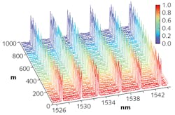
Very recent developments, such as the introduction of a high-precision, akinetically swept, all-semiconductor laser from Insight Photonic Solutions (Lafayette, CO), enables the picometer interrogation resolution required for many applications.6 Using this laser, the WDM/TDM concept can be expanded into a wavelength-to-time approach that interrogates potentially thousands of weakly reflecting FBG elements. This optical time-domain reflectometry (OTDR) scheme converts the return signals generated via a rapidly wavelength swept (at microsecond rates) and pulsed laser input into arrival-time signatures for each FBG in a serial network of sensors (see Fig. 2).Interferometric techniques
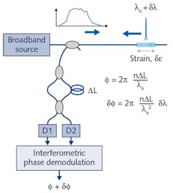
Another novel sensing configuration for dynamic strain (such as vibration) uses an interferometer to decode FBG wavelength shifts (see Fig. 3). Here, the interferometer path difference must be less than the effective coherence length of the light reflected from the grating, which is approximately equal to the length of the grating. This technique is extremely sensitive to dynamic Bragg wavelength shifts, demonstrating a resolution of <600 pε/√Hz.7The Digonnet group at the Stanford Photonics Research Center (SPRC; Stanford, CA) has demonstrated an extraordinarily high-sensitivity FBG sensor using an interferometric resonant cavity and slow light concepts. In fact, dynamic strain sensitivity was reported at 120 fε/√Hz—sufficient to detect thermal phase noise in the fiber cavity.8
Fiber Bragg gratings are also ideal for use as spectrally narrowband reflectors for creating cavities for in-fiber lasers of interest in both telecommunications for tunable single-frequency devices for WDM networks and in the sensing field for strain, particularly for very high-resolution dynamic strain monitoring.
The basic form of an FBG laser sensor (FBGLS) uses either two gratings of matched Bragg wavelength to create an in-fiber cavity, or one grating with a broadband reflector. Doped fiber between the gratings provides cavity gain and thus lasing with appropriate pumping. Several sensor array variations using WDM with this concept have been reported and FBGLSs can be as short as 2–3 cm in length.
FBG sensor applications
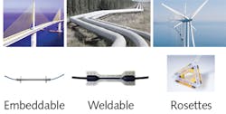
While the application space has been very diverse, the number-one driver for FBG sensors has been infrastructure monitoring of smart structures like bridges, dams, pipelines, and for the aerospace industry. By monitoring load, strain, temperature, vibration, and even liquid or gas flow, structural integrity can be assessed and tracked on a real-time basis (see Fig. 4).The downhole oil and gas industry has a long record of supporting advances in sensor technologies, including optical fiber systems and Raman distributed temperature sensors for in-well temperature and reservoir/production monitoring, fracking, cementing, and exploration activities such as seismic sea-bed testing. Many of the early successes in FBG commercialization were realized in the oil and gas market.9 Distributed sensing is also common in the wind power industry for measurement of stress and strain in turbine blades.
For medical instrumentation, the ability to perform multiplexed sensing along a single fiber with tens of sensor points in an electrically passive format with small size and EMI immunity is very attractive for certain medical procedures. In medical applications, fibers can be inserted in hypodermic needles or catheters, providing minimally invasive yet precise localized positioning of the sensors.
A notable first application of FBGs in vivo was published by Roa et al., where gratings were used for temperature profiling near internal organs in patients undergoing nuclear magnetic resonance (NMR) imaging.10 Further application of temperature profiling has been focused around thermal ablation, a medical procedure often used in cancer therapy. And one of the most advanced uses of FBG arrays is for endoscopic/colonoscopic pressure profiling, wherein localized pressure bends the grating slightly and the wavelength shifts indicate the pressure profile of up to 70 gratings along an array (see Fig. 5).11Additional advances in grating writing technologies include point-by-point writing using femtosecond pulsed near-infrared lasers to create so-called regenerated gratings capable of coping with high temperatures and harsh environments, such as those in power plants (e.g., coal gasification reactors and gas turbines) and combustion and jet engines. When application temperatures reach 1000°C, such FBG sensors are crucial.13
More recent years have seen sensing approaches based on sophisticated processing concepts. For example, Thevenaz et al. and other groups have focused on microwave-photonic-filtering-based interrogation of very closely spaced FBGs to form near-continuous distributed FBG sensing capability.14 This approach has also been extended to the concept of writing a very long, but faint grating into an optical fiber to create a true form of distributed FBG sensing called faint long gratings (FLOG). It is envisioned by these authors that FLOGs could be continuously printed over a significant fiber length and interrogated to provide true distributed FBG sensor formats, and 1-m-long FBG sensors have been reported by some research groups.
Leveraging three decades of development, FBG sensors will continue to evolve into the preferred sensor format of choice for many existing and emerging applications.
REFERENCES
1. K. O. Hill et al., Appl. Phys. Lett., 32, 10, 647–649 (1978).
2. G. Meltz et al., Opt. Lett., 14, 15, 823–825 (1989).
3. G. Meltz et al, Proc. Int. Conf. Optical Fiber Sensors, ThBB5, New Orleans, LA (1988).
4. A. D. Kersey et al, J. Lightwave Technol., 15, 8, 1442–1463 (1997).
5. M.A. Davis et al., Electron. Lett., 32, 1393–1394 (1996).
6. M. P. Minneman et al., Proc. SPIE, 8311, 1–10 (2011).
7. A. D. Kersey et al., Electron. Lett., 28, 236–238 (1992).
8. H. Wen et al., IEEE Sensors J., 12, 1, 156–163 (2012).
9. A. D. Kersey, IEICE Trans. Electron., E-83C, 3, 400–404 (2000).
10. Y. J. Rao et al., J. Biomed. Opt., 3, 1, 38–44 (1998).
11. J. W. Arkwright et al., Opt. Express, 17, 25, 22423–22431 (2009).
12. J. Albert et al., Laser Photonics Rev., 7, 83–108 (2013).
13. S. J. Mihailov, Sensors, 12, 2, 1898–1918 (2012).
14. L. Thevenaz et al, Proc. SPIE, 9157, 91576W (2014).
Alan D. Kersey is president and chief scientific officer at CytoVeris, South Glastonbury, CT; e-mail: [email protected]; www.cytoveris.com.
