Adaptive optics takes tissue imaging to the next level
Could adaptive optics be the next big advance in microscope design?
By Peter Kner and Zvi Kam
It is said that Aristotle, in one of his morning walks, noted the magnifying power of a drop of mildew on a leaf. If true, microscopy is as old as the classical cultures. Compound microscopes have been used in biological research since 1655, when the first of their kind enabled the discovery of cells. Since then, every improvement in the optical design of microscopes and each newly developed technique have led to a breakthrough in biology and medicine.
High-resolution microscopes are designed to take a two-dimensional picture of a thin sample, and many microscopy applications are specifically geared to take advantage of this ability. Sample preparation procedures have been optimized for thin samples, so that the objects of interest are not too deeply embedded in tissue and thus can be easily seen by the microscope. But biology is three-dimensional and, to that end, what biologists would really like in many instances is a three-dimensional image of the cell, tissue section, or embryo.
Over the last 25 years, there has been increasing interest in three-dimensional imaging.1 Three-dimensional images are typically acquired by moving the focal plane of the microscope systematically through the sample starting from the surface. For applications requiring the highest resolution (approximately 200 nm in the imaging plane), oil immersion lenses, which enable imaging up to roughly 50 µm into the sample, are used
High-resolution microscopes are optimized for imaging just at the surface of the sample, usually under a glass coverslide. Since the sample itself is optically inhomogeneous and has a different refractive index than the glass, the image quality rapidly degrades as the imaging plane moves deeper into the sample. Due to the refractive-index difference between the oil and water, the peak intensity of a point source will be weaker by a factor of four, just 30 µm deep in water compared to the peak intensity at the coverslip when using an oil-immersion objective and a numerical aperture (NA) of 1.2.
In addition, the width of the image in the axial direction will be more than two times larger, resulting in a loss of axial resolution. In a complex biological sample with varying refractive indices, the degradation will be even more pronounced. Current research that uses microscopy has a growing need to identify specific substructures inside cells and embryos where there is a strong unavoidable background. This task can only be accomplished by optimizing the signal quality to detect weak molecular signals. Because the impact of lost signal intensity can be so significant on image quality, the benefit to correcting these aberrations is incredibly important for biological imaging.
Correcting distortions
Our group at the University of California, San Francisco (UCSF), along with other academic research groups worldwide, is using adaptive optics to correct the optical distortions in three-dimensional biological imaging. Although the technology was originally developed for astronomy, it is now being used to enable high-resolution optical microscopes to collect three-dimensional images with the highest optical resolution and signal intensity throughout the sample.
Adaptive-optics applications require two technologies: an adaptive or deformable mirror and a wavefront sensor. A deformable mirror is a mirror whose surface can be locally deformed by a grid of actuators that control the position of the mirror surface. The deformable mirror compensates the wavefront of a distorted optical wave by creating a shorter path length where the wavefront is retarded and creating a longer path where the wavefront is advanced. The wavefront sensor measures the wavefront so that the deformable mirror can be set to create a flat wavefront.
At UCSF, we are using adaptive-optics technology to correct for depth aberrations in three-dimensional wide-field microscopy. One of the main sources of aberration in three-dimensional imaging arises from the combined refractive-index differences of the sample, the coverslip, and the immersion oil. High-resolution objectives are designed to image through immersion oil and the coverslip to achieve the highest resolution (because the wavelength of light is smaller in higher-index material), but refraction at the interface with the sample distorts the wavefront. Depth aberrations are proportional to the depth below the coverslip so the image quality degrades in proportion to depth.
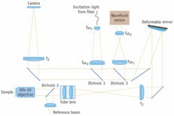
Because the depth aberrations are caused by the interface between the sample and the coverslip, the wavefront distortion can be theoretically calculated, and the deformable mirror can be set to correct the aberration for a given depth in the sample.2 Correcting depth aberrations is an open-loop configuration of adaptive optics. In the adaptive-optics microscope the focal plane of a high-resolution microscope is re-imaged onto a CCD camera with the deformable mirror inserted at a position conjugate to the back focal plane of the objective (see Fig. 1). By placing the deformable mirror in the back focal plane, the depth aberrations are corrected over the whole field of view of the microscope.
FIGURE 1. In the adaptive-optics microscope used at UCSF, the focal plane of a high-resolution microscope is re-imaged onto a CCD camera with the deformable mirror inserted at a position conjugate to the back focal plane of the objective.
The deformable mirror is not only used to correct for depth aberrations, it can also be used to focus rapidly into the sample. If the mirror shape is set to correct for not just the refraction at the sample-coverslip interface, but equally for the path length difference between focusing at the coverslip and focusing a depth “d” into the sample, the system will image the plane at depth d below the coverslide. This ability is incredibly important for applications that require rapid three-dimensional imaging. If the focusing is done by moving the sample, the rapid movement will shake the sample. Focusing with the deformable mirror allows rapid focusing without moving the sample.
To allow for correcting aberrations and focusing deep into live tissue, we chose to use the deformable mirror from Imagine Optic (Orsay, France), which has a very large stroke. The mirror can generate a maximum peak-to-valley wavefront amplitude of 50 µm, which is several times higher than is possible with other deformable mirror technologies. The mirror can generate spherical aberrations with a maximum amplitude of 8 µm. This means that the mirror can correct first-order spherical aberrations up to 350 µm into water with an oil-immersion lens using an NA of 1.2. In practice the depth is limited to roughly 50 µm by the higher-order spherical aberrations which cannot be corrected by the mirror.
Shack-Hartmann wavefront sensor
We also use an Imagine Optic HASO32 Shack-Hartmann wavefront sensor to measure the shape of the mirror and set the shape for a given depth into the sample. The wavefront sensor software is very responsive and was easily integrated into our own programs, allowing rapid setting of the mirror shape. We are using a reference beam from a HeNe laser as the source for the wavefront measurements. In the future, we plan to use the wavefront sensor to measure the wavefront directly from the sample so that the deformable mirror can be operated in a closed-loop for correcting sample-induced aberrations.
The challenge here is that wavefront measurements from biological samples are difficult to work with because the signal is weak and the samples frequently do not have natural point sources that can be used for wavefront measurements. To work around this problem, many research groups have used search algorithms to optimize the mirror shape, but this requires acquisition of several additional images which can be a problem in samples with weak signals that bleach rapidly. One of the advantages of our method is that it does not require such excessive exposures.
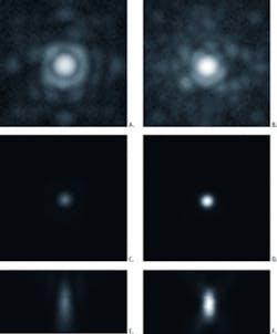
FIGURE 2. Images of a 200 nm bead 57 µm below the coverslip are shown uncorrected at left: in-focus lateral plane (top), in-focus image on a log scale (center), and through-focus image (bottom). The corresponding images of the bead corrected with adaptive optics are shown at right.
Images of a 200 nm bead 67 µm below the coverslip in a liquid with index 1.42 are compared before (left) and after (right) correction (see Fig. 2). Correcting the depth aberrations increases the peak intensity by a factor of two. In addition to increasing the peak intensity, correcting the depth aberration improves the shape of the 3-D point-spread function (PSF; the image of a point source of light). This is important because it reduces the width of the image in the axial direction, restoring lost axial resolution.
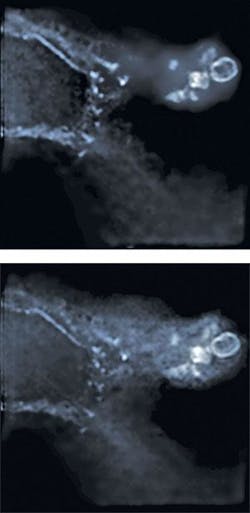
Improving the shape of the 3-D PSF is important for deconvolution, which provides optical sectioning in wide-field microscopy by restoring the emitted light to its point of origin.3 Correcting for depth aberrations converts a depth-dependent deconvolution problem into a space invariant problem, allowing the use of fast iterative deconvolution algorithms and thus improving the quality of deconvolved images. Deconvolved images of actin stained with Alexa488-Phalloidin in B16F10 mouse cells were taken with and without correcting depth aberrations (see Fig. 3). It is clear that the deconvolved image taken with correction of depth aberrations is sharper with lower background noise than that taken without correcting depth aberrations.
While the results so far show that it is possible to improve imaging by correcting depth aberrations with adaptive optics, we believe that we have not yet reached the full potential for adaptive optics in microscopy. One of the most important applications for adaptive optics in microscopy is imaging into live tissue. In this case, the refractive index of the sample cannot be modified by sample mounting methods, and the ability of the deformable mirror to both focus and correct sample-induced aberrations rapidly will be incredibly important. By carefully understanding both the depth aberrations and sample-induced aberrations, it should be possible in the coming years to dramatically improve image quality deep into strongly distorting live samples using adaptive optics.
References
- D.A. Agard, and J. W. Sedat, Nature 302, 676(1983).
- Z. Kam, P. Kner, D. Agard, and J.W. Sedat, J. Microsc. 226, 33 (2007).
- J.R. Swedlow, J.W. Sedat, and D.A. Agard, “Deconvolution in Optical Microscopy,” in Deconvolution of Images and Spectra, P. A. Jansson, ed. (Academic Press, Inc., San Diego, CA, 1997), pp. 284-307.
PETER KNER is an optical physicist at the Sedat Lab at the University of California, San Francisco, and ZVI KAM is a professor of biophysics at the Weizmann Institute of Science, Rehovot, Israel, at UCSF. Contact Kner at [email protected].


