Novel Detectors: SPADs offer possible photodetection solution for ToF lidar applications
A self-driving car, once a technological fantasy, is likely being tested on some road at this moment. It has the potential of being a disruptive innovation—changing the way we live—if science and technology make it safe enough to be adopted by the general public.
Driving, especially in an urban environment, is a complex task, requiring a continuous stream of sensory information about the surroundings. A momentary lapse of the driver’s awareness, or lack of the relevant information, can lead to a fatal accident.
Humans drive instinctively: we do not calculate distances or speeds, we just somehow know what they are. A self-driving car, a machine, has no instinct. All driving “decisions” are based on real-time calculations of sensory inputs, such as distance, speed, color, or shape.
These inputs must be obtained with onboard sensory systems. A high-resolution, three-dimensional spatial view of the car’s surroundings is probably the most critical information needed—light-detection and ranging (lidar; also widely known as LiDAR) is a system that can provide this information.1
Light probing
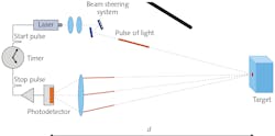
Lidar probes the surroundings with light. One approach, known as scanning time-of-flight (ToF) lidar, uses a laser that emits a pulse of light (see Fig. 1). At the instant of emission, an electronic clock is activated. The beam-steering mechanism directs the pulse in the desired direction. The pulse reflects from the target, and some fraction of the reflected light passes through the detection optics towards the photodetector.
In response, the photodetector, coupled to the frontend electronics, creates an electrical signal that deactivates the clock. The measured time of flight, Δt, allows the calculation of the distance, d, to the reflection point, namely =12cΔt, where c is the speed of light in the medium where the measurement is being made.
Duration of the pulse and its peak power are two crucial parameters. The first determines the distance resolution, while the second the maximum measurable distance. Simply stated, the ToF concept favors short-duration and high-peak-power pulses. The current designs achieve ~5 ns for the duration and ~100 W for the peak power. Sensing such pulses requires that the detection bandwidth is approximately equal to the inverse of the pulse duration, or ~200 MHz.
Only a tiny fraction of the light emitted by the laser reaches the photodetector. The actual amount depends, among other factors, on the distance to the target, the target’s reflectivity, and atmospheric conditions.2 In addition, the weak light signal is mixed in with information-less background (solar radiation, streetlights, or headlights).
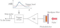
In a basic analog detection system (see Fig. 2), the narrowband optical bandpass filter blocks out, though not completely, the background light. The photodetector, either a linear-mode avalanche photodiode (APD)3 or a silicon photomultiplier (SiPM),4 outputs a current pulse in response to the incident light.The transimpedance amplifier converts the current pulse to the voltage pulse. If the instantaneous value of the voltage rises above some specified level, the trigger circuit stops the timer, giving the time of flight. This looks simple enough, so why is photodetection in ToF lidar challenging?
A noisy problem
The short answer is noise. The weak light signal, which already has an intrinsic noise (photon shot noise), has to compete with noise coming from several sources: unfiltered background, dark current and gain variation of the photodetector, and the amplifier. The measured distance uncertainty, approximately given by:
improves, for a given detection bandwidth B (set by the pulse duration), with increasing signal-to-noise ratio, S/N, of the detected light signal.
The ratio must be greater than 1 for the detection to have any useful information, and the higher the ratio, the more accurate the distance measurement. The challenge is to maximize the S/N. Doing so for a given input light level favors a photodetector with a high spectral photosensitivity, high intrinsic gain with a small noise penalty (excess noise factor), low dark current, and small terminal capacitance.
Additional desirable features are a minimal time jitter and high dynamic range. Since no single photodetector exists that satisfies all of the above requirements, an actual engineering design involves numerous tradeoffs.
It is beyond the scope of this article to discuss these intricate compromises. Instead, the remaining sections focus on a photodetector, single-photon avalanche photodiode (SPAD),5 that only recently has found its way into designs of ToF lidars.
The structure of a SPAD is similar to that of an APD. Both have a p-n junction within which there is a high-field region where a charge-carrier multiplication, or avalanche, occurs due to impact ionization. The avalanche can be triggered by an injection of a conducting electron or a hole into the high-field region. Prior to the injection, the pair ensued either from a photon absorption, thermal fluctuation, or tunneling event; the latter two constitute dark counts.
Nature of avalanche
The main difference between the two devices is the nature of the avalanche or discharge. The reverse bias voltage, VBIAS, on the SPAD is greater than the breakdown voltage, VBD; this is known as Geiger mode. If VBIAS across the SPAD is fixed, once triggered, the avalanche goes on in perpetuity, yielding infinite gain—one photon has caused a constant flow of current. In contrast, VBIAS, applied to a linear mode APD, is below VBD. A discharge, once started, rapidly self-quenches, producing a current pulse containing a finite amount of charge—consequently, the gain is finite.
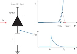
As described above, a single incident photon can activate the SPAD, starting a perpetual current. Effectively, the photon has switched the SPAD from an off to an on state, or from a photosensitive state to a photo-insensitive state (a SPAD with an ongoing discharge is no longer photosensitive). This is a light switch, but to be useful in detecting the next incoming photon, it is necessary to bring back the SPAD to the off, or photosensitive, state again, which can be done using a resistor in a passive quenching approach (see Fig. 3).The left panel of Figure 3 shows a reverse-biased SPAD in series with a resistor R. The SPAD is in the off state: no current flows and the voltage across the SPAD is vBIAS. The SPAD is in a metastable, photosensitive state. The red dot on the I-V characteristic (top-right panel) depicts this configuration. Since no current flows, the voltage on the resistor vR=0.
Suppose the SPAD absorbs a photon, triggering Geiger discharge at an instant tA (see the lower-right panel in Fig. 3). The current starts to flow, increasing rapidly. Because the Kirchhoff voltage rule must be satisfied at all times, as the current increases, the voltage across the resistor increases, while the voltage across the SPAD decreases.
Once the voltage across the SPAD drops to o ~VBD, the electric field in the p-n junction can no longer sustain impact ionization and the avalanche stops. The quenching occurs when vR reaches the peak value. Subsequently, the SPAD enters the recovery stage: the current decreases, while the voltage on the SPAD increases, eventually returning back to VBIAS; the SPAD is now fully light-sensitive again.
The voltage waveform depicted in the lower-right panel of Figure 3 is effectively the measurable output in response to a single photon (or dark event). The waveform is asymmetric, characterized by a very short rise time (~1–2 ns) and much longer fall time (~tens to hundreds of nanoseconds).
Junction capacitance
The latter, affecting the recovery time, depends on the SPAD’s junction capacitance, CJ, and the value of the quench resistor R. During the recovery, the SPAD is insensitive to light* and the duration of the recovery is referred to as the SPAD’s dead time. The area under the curve, expressed in electrons, is the gain. Surprisingly, the gain does not depend on R; instead, it is linearly proportional to the product CJ(VBIAS-VBD, where the quantity in the parentheses is referred to as overvoltage.Some of the key optoelectronic characteristics of a SPAD are photon detection efficiency, gain, and dark count rate. A SPAD can be activated by a single photon, but this photon could be part of the background and not the signal, so how can this device be used to measure distance in ToF lidar?
In the simplest setup (but also see, for example, Ref. 6), the laser emits a sequence of short-duration pulses, separated in time by a period T, for a given point on the target. This means that the target is illuminated repeatedly.
On the detection side, for each period T, one measures the time intervals, Δt, between the instant of the pulse emission and the SPAD’s trigger times. Although the SPAD can be triggered by a dark event, background photon, or the signal photon, if tens, or hundreds, of thousands of measurements are made, a histogram of the trigger times will show a peak at Δt equal to the round-trip time to the target because dark events and background photons trigger the SPAD at random times, while the signal can only trigger at a specific time—the round-trip time.
In the absence of dark events and the background, the histogram of the trigger times would consist of events tightly clustered around the roundtrip time, with the width of the distribution affected mainly by the pulse duration and the SPAD’s time jitter. In the presence of dark events and background light, the distribution broadens, and events appear for all bins.
Infinite background
In the limit of infinite background, the histogram is flat, containing no information. Automotive lidar must be able to operate under all lighting conditions, even in bright daylight. Here, however, histogram broadening, or even flattening, is a real possibility.
To alleviate the influence of the background, one can alter the measurement technique to include spatial and temporal correlation. To do so, instead of using a single SPAD, let’s use, for example, four SPADs that together comprise a single photodetection element (see Fig. 4).The red and green bullets represent signal and background photons, respectively. The background photons arrive at the four elements of the SPAD array randomly, making it unlikely that all four SPADs activate within some narrow time window. Because there is no spatial coherence (less than four SPADs active) and no temporal coherence (the SPADs do not activate at the same time), the triggers due to background photons can be discounted.
However, the signal photons travel as a group, and so when they impinge on the SPADs, their nearly simultaneous triggers are likely. This event would be counted and included in the histogram. Detection based on spatial and temporal coherence can make the measurements less sensitive to the background and some types of noise, such as gain variation and amplifier noise.
But, as it is common in the engineering designs, an improvement almost always comes at some cost. In this approach, the drawbacks are longer data acquisition times and more-complex data processing. Will the pros outweigh the cons? Only time will tell.
* This statement is not completely true. During the recovery, as the voltage on the SPAD increases and is above VBD, the probability of Geiger discharge is not 0. There can be avalanche during the recovery stage, albeit with a smaller gain. The phenomenon of afterpulsing is the evidence.
REFERENCES
1. R. H. Rasshofer and K. Gresser, Adv. Radio Sci., 205–209 (2005).
2. J. Wojtanowski et al., Opto-Electron. Rev., 183–190 (2014).
3. P. P. Webb, RCA Review (1974).
4. A. G. Gasanov, V. M. Golovin, Z. Y. Sadygov, and N. Y. Yusipov, Lett. J. Tech. Phys., 16, 14 (1990).
5. R. H. Haitz, J. Appl. Phys., 1370–1376 (1964).
6. M. Beer, Sensors, 18, 12, 4338 (Dec. 2018).
About the Author
Earl Hergert
VP of Marketing, Hamamatsu
Earl Hergert is VP of Marketing at Hamamatsu (Bridgewater, NJ).
Slawomir S. Piatek
Hamamatsu Corporation
Slawomir S. Piatek has been measuring proper motions of nearby galaxies using images obtained with the Hubble Space Telescope as a senior university lecturer of physics at New Jersey Institute of Technology. He has developed a photonics training program for engineers at Hamamatsu Corporation in New Jersey in the role of a science consultant. Also at Hamamatsu, he is involved in popularizing a SiPM as a novel photodetector by writing and lecturing about it, and by experimenting with the device. He earned a Ph.D. in Physics at Rutgers, the State University of New Jersey.


