A sensor design derived from the vision system of a common housefly overcomes some of the shortcomings of CCD and CMOS arrays.
CAMERON H. G. WRIGHT, ROOPA S. PRABHAKARA, and STEVEN F. BARRETT
Computer vision requires sensitive and accurate imaging sensors, preferably with fast response times. Charge-coupled-device (and CMOS) arrays have dominated the field in recent years because of their reliable performance and relatively affordable cost. However, these sensors offer less than satisfactory performance in certain imaging scenarios.1 For example, when a relatively small object moves very quickly across the sensor array’s field of view (FOV) the rapid integration time of an individual pixel limits detection of the object. Further, if the image contrast is poor, whether due to lighting or object color compared to the background, the problem is exacerbated.
For a real-world example, imagine a remotely piloted vehicle navigating the low-altitude airspace of a typical city. The vehicle must navigate around many obstacles that pose significant threats, such as power and telephone lines that are extremely difficult to detect with traditional imaging sensors. There is also a high probability of collateral damage to power or communications infrastructure and to personnel on the ground if the vehicle cannot avoid such obstacles. Traditional CCD sensors may not be the best approach for this type of situation.
In recent years, other sensor designs have been proposed as alternatives to CCD and CMOS arrays, in particular designs derived from known biological vision systems. The fly-eye sensor, based on Musca domestica (the common housefly), is one such biomimetic imaging device.3 This patent-pending vision system, developed by the Wyoming Information, Signal Processing, and Robotics (WISPR) Laboratories of the University of Wyoming (Laramie, WY), in collaboration with the U.S. Air Force Academy (Colorado Springs, CO), is intended to overcome some of the shortcomings of traditional sensors, especially for situations involving small, fast-moving objects in low-contrast situations.2
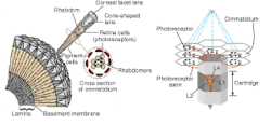
We have devised an artificial front-end sensor that replicates nearly all the attributes of the biological fly eye (see “How a fly’s eye works,” p. 64). This sensor is an inherently analog system that mimics the highly parallel retinal processing in the fly’s compound eye (see Fig. 1). Results based upon software simulations of our fly-eye vision system suggest superior motion-detection capabilities in low-contrast conditions due in part to the staggered hexagonal configuration of the cartridges and the overlapping fields of view. Recently developed hardware prototypes have begun to confirm the validity of these simulations.7
Comparing the fly eye and CCD
Researchers at WISPR compared the performance of a traditional CCD imaging array in a commercially available RS-170 camera with the biomimetic fly-eye sensor for several imaging scenarios. The fly-eye sensor is part of a unique vision system in which we have applied a parallel design evolution of the vision sensor as well as the processing circuitry that mimics the visual cortex.4 In the tests, we concentrated on the capabilities of the front-end vision sensor only; the complete vision-system performance will be tested as development progresses.
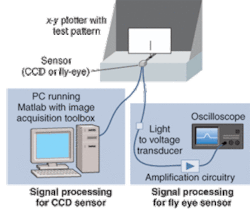
For the initial tests, we wanted to obtain quantitative comparisons of the fly-eye sensor and an inexpensive CCD array for detecting small moving objects in both high- and low-contrast situations. We constructed a fly-eye sensor array in which each photodetector for an artificial cartridge used a ball lens for the front-end optics and an optical fiber to transmit captured photons to the signal-conditioning circuitry. The optics resulted in a photodetector FOV of nearly 53° (with a Gaussian response) and an effective focal length of 12 mm. The signal conditioning used TAOS TSL250R phototransducers and some low-noise operational amplifiers; a storage oscilloscope was used as the output display.
For the CCD array, we chose a Sony XC‑75 camera, using an RS-170 (EIA) interface to a Data Translation DT3120 frame grabber installed in the PCI bus of a standard “Wintel” PC. The XC-75 incorporates a 1/2-in. CCD array with 768 × 494 active elements. The frame grabber digitized the analog video signal to 8-bit pixel values and assembled them into a 640 × 480 format under control of the Matlab Image Acquisition Toolbox. The lens used was a Nikkor 55-mm, f/2.8-f/32 macro lens. This lens required refocusing each time the object distance with respect to the sensor was changed for our tests. For the CCD camera, some signal conditioning (other than the internal camera electronics) is due to the frame grabber (see Fig. 2).
Testing
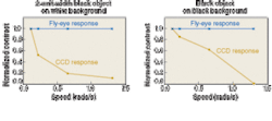
We conducted four series of tests, two with high contrast and two with low contrast. For the high-contrast test using a simple test pattern of a thin black vertical line on a white background, we first moved the pattern horizontally across the test sensor array’s overall field of view at various speeds, at a distance of 108 mm from the sensor array’s focal plane (see Fig. 3, left). While we used lines of three different widths (2%, 4%, and 10% of the CCD array horizontal FOV), the same relative shape of the normalized response curves was observed in each case.
Note how the fly-eye sensor’s ability to detect the object is nearly unaffected by speed, but the CCD has difficulty with faster-moving objects. We then moved this same test pattern out to a distance of 356 mm from the focal plane, and slowly moved the test pattern a horizontal distance of only 1 mm back and forth (movement equivalent to approximately 2.8 mrad). The fly-eye sensor was able to detect such small movement for all three line widths; the CCD array was unable to detect any movement.
In the low-contrast test we used a nearly black background with the same procedure. For the object, we tried gray and black (separately), placed vertically against the black background. The results were very similar to the high-contrast tests. While the magnitude of the response of both types of sensors was lower in the low-contrast situation (as expected), the relative performance between the fly-eye sensor and the CCD was very similar. For the small-motion tests (at an object distance of 356 mm), the fly-eye sensor was once again able to detect very small movement, even of the black object; the CCD array was once again unable to detect such a small movement (see Fig. 3, right).
The results of these preliminary tests are intriguing. Biologists have predicted that a fly-eye type of sensor would be very sensitive to motion, even in low-contrast situations. Simulations tended to support this, and now the first tests of prototype hardware also show this. It appears that the fly-eye sensor would be able to detect motion, even of fast-moving small objects, in demanding lighting situations. While the fly-eye sensor will not take the place of CCD arrays, it should provide an excellent added imaging capability for computer vision and mobile robots. More extensive testing is planned by WISPR Labs personnel.❏
REFERENCES
1. J. Nakamura, Image Sensors and Signal Processing for Digital Cameras, CRC Press (Taylor and Francis), 2006.
2. D.T. Riley, S.F. Barrett, M.J. Wilcox, C.H.G. Wright, Proc. SPIE 12th Int’l. Symp. Smart Structures and Materials: Smart Sensor Tech. and Meas. Systems Conf. (SPIE 5758) (March 2005).
3. M.J. Wilcox, D.C. Thelen, Jr., IEEE Trans. Neural Net. 10, 574 (May 1999).
4. C.H.G. Wright, S.F. Barrett, D.J. Pack, ISA Biomed. Sciences Instrumentation41, 253.
5. K. Nakayama, Vision Research25, 625 (1985).
6. T. Poggio, M. Fahle, S. Edelman, Science256,1018 (1994).
7. R.S. Prabhakara, C.H.G. Wright, S.F. Barrett, W. Harman, Proc. SPIE 18th Int’l. Symp. Electronic Imaging (SPIE 6068) (January 2006).
How a fly’s eye works
While most readers of Laser Focus World are familiar with CCD arrays, many are probably unfamiliar with the highly modular eye design of a common housefly, which provides the inspiration for this new sensor. The ommatidium is the major structural unit for the front end of the fly’s vision system, and is composed of a 25-µm corneal facet lens at the surface, a cone-shaped lens, and a pack of photoreceptors. Deeper into the structure of the ommatidium is the lamina, including the L1 and L2 monopolar cells, which are part of the medulla (or vision processing circuitry). The compound eye contains about 3000 of these “miniretinas,” each consisting of six hexagonally placed peripheral photoreceptor cells, and two central photoreceptors. The photoreceptors R1-R6 contain rhabdomeres (collectively called a rhabdom), and transducers to convert photons into an ionic current. The central photoreceptors R7 and R8 are connected to the medulla (processing circuitry) and are not a part of the front-end imaging system.
Each peripheral photoreceptor shares a nearly identical view with a photoreceptor from each closest neighbor ommatidium, and the overlapping Gaussian-shaped responses lead to hyperacuity (analogous to subpixel resolution).5, 6 Gap junctions connect these common view photoreceptors from the adjacent ommatidium to monopolar cells such as L1 and L2 for processing. The processed output from the monopolar cells, depending on the specific neural layer and interconnections, is an encoded signal containing extracted image information such as position, velocity, and edges of objects in the image. This structure-composed of the common view photoreceptors from separate (but adjacent) ommatidia-together with the gap junctions and the L1 and L2 monopolar cells make up what is called the cartridge.
CAMERON H. G. WRIGHT is an assistant professor, ROOPA S. PRABHAKARA is a graduate student, and STEVEN F. BARRETT is an associate professor in the department of electrical and computer engineering at the University of Wyoming, 1000 E. University Ave. Laramie, WY 82071; e-mail: [email protected]; www.eng.uwyo.edu/electrical/faculty/wright.


