ANDY WHITEHEAD
High-speed imaging using CCD or CMOS cameras enables spatial and spectral measurements that were not possible until recently. However, high speed also imposes severe burdens on the supporting electronics in terms of memory, digital interface, and host-processor overhead—and can limit speed or accuracy in many applications. We have implemented data-reduction algorithms running on processors inside a camera that preserve the speed and accuracy of the original sensor with minimal increase in host-processor overhead. Wavefront sensing and high-speed spectroscopy are two applications benefiting from this technology.
Smart cameras
Cameras that acquire and transmit images only are considered “dumb.” Intelligence is required whenever information contained in an image is extracted and transmitted, whether or not the image is sent out as well. Smart cameras have been used to perform a broad range of tasks in the machine-vision world: linear measurements, autonomous recognition of an object in the field of view, thresholding, contrast enhancement, JPEG or MPEG compression, binarization, and color correction, to name a few. Many applications require cameras for nonimaging tasks, and these are generally good applications for smart cameras.
Data reduction using a smart camera depends on the application. In some cases, very high-resolution smart cameras are used for just a few critical linear dimensions leading to data reduction of five to six orders of magnitude. On the other hand, an unsharp mask or convolution algorithm may not reduce the data at all; instead, complex but necessary preprocessing is moved into the camera, freeing up resources in the host computer for subsequent data reduction.
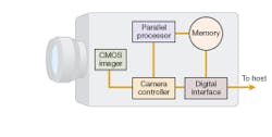
Smart cameras traditionally use image sizes of 640 x 480 pixels or below and frame rates less than or equal to 60 Hz. We have developed a smart camera that uses embedded high-speed processors, has a 1.3-megapixel array size and frame rates of 500 Hz to 500 kHz, and processes imagery in real time for laser-based measurements (see Fig. 1). The USB-2 interface does not require a frame grabber and implies a minimum data-reduction factor of 40 to convert the 820 MByte/s data rate from the imager to the 21 MByte/s sustained data rate supported by USB-2.
Typical high-speed image-reduction tasks use pipeline- and parallel-processing techniques. Pixel values are read into a “pipeline” until the pipeline is full, and then each successive operation completes one step in the processing process. A known latency exists that is associated with filling up the pipeline; however, once the pipeline is full, processing proceeds at high speed. Parallel processing involves an array of independent processor architectures that may or may not perform the same tasks on all pixels. The most advantageous case for high-speed parallel processing would be to have one processor for every pixel. This ideal is not realistic for megapixel cameras, however, which leads to a compromise between speed and resources. For the very high frame rates required for the applications below, a combination of pipeline- and parallel-processing techniques is used.
In Shack-Hartmann sensors
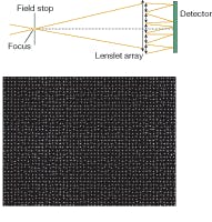
A common nonimaging application for cameras is found in a Shack-Hartmann sensor. The Shack-Hartmann sensor measures the local curvature of a beam of light at multiple points across its aperture after it propagates through a medium or reflects from a surface. If the incident beam of light has a known structure (for example, monochromatic, spatially filtered, and planar), then the wavefront properties of the test beam yield valuable information about the propagation medium or reflected surface. To sample a wavefront at multiple locations, a lenslet array is positioned over the imager to create many (typically several thousand) spots of light.
The deviation of each spot centroid from that produced by the original structured light contains information about the wavefront error within the region (typically several hundred microns in size) of the wavefront sampled by each lenslet.
A Shack-Hartmann image needs high resolution for statistical accuracy but contains little useful information for the human eye (see Fig. 2). Because of this, there is no need for image storage other than diagnostics. However, rapid data reduction is critical for many applications. For example, imaging systems looking long distances through the atmosphere suffer from atmospheric turbulence that induces aberrations in the scene. These fluctuations occur in a millisecond time frame and are entirely unpredictable. To correct for these atmospheric effects, a feedback loop needs to sample the wavefront across the image aperture, determine centroid deviations, and apply drive-signal corrections to a deformable mirror at kilohertz rates based on this instantaneous wavefront sampling.We have demonstrated centroiding processes running inside the camera for a 1280 x 1024 image size at 500 frames per second and a 640 x 480 image size operating at a 1 kHz frame rate. Areas of interest (AOIs) around each spot are defined and centroid data calculated for each AOI. Data returned over the USB-2 interface are three 32-bit values: x-centroid, y-centroid, and total sum of AOI intensity. Data rates were reduced from 820 Mbyte/s for 1280 x 1024 10-bit images at 500 frames per second to 19.6 Mbyte/s for centroid data. The CMOS imager can be windowed down to run at frame rates up to 16,000 frames per second while still supplying reduced centroid data. The amount of data reduction varies for different wavefront-sensor configurations (see table).
Accuracy and reliability, as well as speed, of the centroiding process are critical. A Labview (National Instruments; Austin, TX) routine running on a serial processor verified the embedded processing to 32-bit accuracy. Although the camera developed here for wavefront sensing was sensitive to the visible spectrum, implementation in the IR or UV regions is limited only by the availability of high-speed imagers in those wavelength ranges.
Application to high-speed spectroscopy
Although smart cameras have no dispersive elements with which to generate spectra from a source, they can be coupled with spectrometers to sample and identify spectral features at rates up 500 kHz with dynamic range up to 84 dB. To accomplish this, the area-scan sensor in the camera was driven in line-scan fashion, generating multichannel spectra up to 1280 x 1. The 12 µm pixel size is small enough for high-resolution spectral measurements and the ability to bin rows increases dynamic range at the expense of sample rates. The onboard processing makes feasible pattern matching of captured spectra to a known database at kilohertz rates.
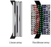
One of the many attractive features of a smart camera for high-speed spectroscopy is its ability to be reconfigured for many different applications. One example of this is the recording of low-light spectra from a monochromator with curved exit slits. A simple linear-array detector offers limited resolution because of its vertical extent. However, by uploading a software mask to the smart camera, we can define any arbitrary geometric pattern—for example, one that matches a curved exit slit (see Fig. 3). By creating multiple curved detectors arrayed in a linear fashion, high spectral resolution and dynamic range are preserved.The green pixels in the figure define the current exit-slit aperture, with red and blue capturing adjacent spectral regions. As many as 255 different geometric regions can be defined with arbitrary pixels for a 255 x 1 custom “curved” detector array sampled at 500 frames per second or higher. All pixels in a region are binned, thereby increasing the signal-to-noise level by √N, where N is the number of pixels per region. A linear array would have a significant reduction in resolution or would be too short to capture the full slit height.
While laser-based metrology demands a number of different photodetectors (single-element PIN photodiodes, quadrant detectors, linear arrays, area arrays, and so on) for different tasks, the photodetection tasks presented here are well-served by SVSi’s smart-camera technology. In each case, speed of measurement and unusual geometries precluded traditional photodetectors. As imager and processing speeds increase in the future, smart cameras will offer more advantages in laser-based measurements.
ANDY WHITEHEAD is chief technology officer at SVSi, 8215 Madison Blvd., Suite 150, Madison, AL 35758; e-mail: [email protected]; www.southernvisionsystems.com.


