Inverse problem stymies
Inverse problem stymies
optical tomography
Igor Khalfin
Optical tomography will be a serious
contender for medical and biological
imaging once details can be derived in vivo from the scattering patterns of near-IR radiation.
Interest in near-infrared (IR) techniques for medical and biomedical imaging has increased in recent years, partially driven by successes in medical-imaging modalities such as magnetic resonance imaging (MRI) and computed tomography (CT), also by successes in optical imaging of the atmosphere.1-3 Near-IR imaging in the body, however, poses a different inverse problem than the other techniques. And that problem must be properly stated and solved before optical tomography can provide meaningful biological details based on patterns of scattered light.
Compared to existing methods for medical and biological imaging, optical tomography offers compelling advantages. It is relatively safe, because it uses no ionizing radiation. It is relatively cheap and portable, because it doesn`t require large magnets or radiation shields. It also offers therapeutic potential in such treatments as photodynamic therapy.
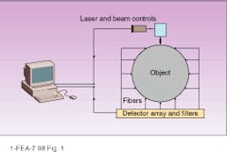
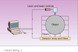
In optical tomography, a light source illuminates an object at some point on the surface, light scatters at the bulk material, and an array of detectors measures intensity of the scattered light (see Fig. 1). The scattering pattern as measured at the detectors can provide a transmission function of the object for a given source-detector configuration. Ultimately solving this inverse problem for optical tomographic imaging (which is actually composed of several nontrivial problems) requires the identification of internal optical properties of the object--based on the measured transmission function between the source and detectors and the restored transmission function for the whole object.
Difficulties of tomographic imaging
The first problems that have to be solved are similar for all tomographic imaging methods. The simple diagram in Figure 1 cannot provide any reasonable spatial resolution because the number of source-detector pairs is much less than the number of pixels to be restored in the bulk. One possibility for improving this situation is to increase the number of source-detector pairs. This can be achieved by scanning the laser over the object, by switching the laser between fibers attached to the different points on the surface, or by moving the source across the surface (as is done with the x-ray signal in computed tomography).
Another possibility is to use prior information about optical properties of the object (as might be obtained, for example, by mapping optical properties onto an MRI image). Such a strategy may simplify finding changes in the object (for example, appearance of tumor) as compared with other approaches. But such an approach can also be complicated by continuous physiological changes in the biological specimen. Motion artifacts present another complication, which can be minimized by contact measurements and fixing the object. Physiological motion (such as heartbeats and breathing) cannot be avoided, however, when imaging physiological systems.
Tomography based on optical imaging presents an additional set of problems that become immediately apparent upon comparing the process with tomography based on other imaging methods. Magnetic resonance imaging allows independent signal acquisition from each pixel, and an image is built as a map of relative change in relaxation time T1 or T2. Atmospheric optical imaging and CT (which records tissue density) are based on the facts that the medium is weakly scattering and weakly absorbing, the distance between scatterers is large in comparison with wavelength, and the dielectric constant changes slowly. So in both optical atmospheric imaging and CT, the scatterings of signal are independent and can be treated in the framework of transport or diffusion theory,4 which usually gives good results.
The key approximation of transport theory is independence of scattering in a multiscattering system where perturbation of the background medium is weak.4,5 The approximation works for imaging in atmosphere and for x-ray CT where the medium is not dense with respect to the wavelength and allows use of projection methods. For optical wavelengths in the body, however, the system breaks down because the distance between scatterers in biological objects presents the same order of magnitude as the wavelength of the near-IR band (about 1 µm). In addition, local deviations of the dielectric constant are strong, so scattering cannot be considered as independent. Biological tissue has pronounced microstructures--biological cells and their organoids (scale of a few microns); blood vessels, skin, bone`s structure (scale of millimeters); different kinds of tissue, for example, organs and fat layers (scale of a few centimeters)--that cannot be considered as noncorrelated.
Despite these considerations, transport theory remains the usual approach to the problem of optical imaging of biological objects, and good results can be obtained with model computations and experiments on phantoms with homogeneous backgrounds (for example, intralipid solutions). Consistently good results with real biological tissues are more difficult to obtain, however, because they are weakly absorbing but strongly scattering in the near-IR region. So methods much more accurate than transport theory must be developed before optical tomography will be able to compete with MRI or CT.
Light-scattering solution
Upon translating these observations into a mathematical framework we find that theoretical studies of multiple scattering media beyond the Born approximation have shown the significance of correlation between instances of scattering.6 And in a diffusive medium the contribution of wave properties of light such as internal reflections and interference are of the same order of magnitude as the contribution of radiative transport, even in the limit when the transport mean free path is large in comparison to the wavelength.7 These effects become more significant across areas of changing dielectric constants.
Analysis of multiparticle dynamics in heterostructures shows that exponentially weak interaction changes the behavior of the system drastically.8 Experimental results show that even thin biological tissue cannot be considered in general as a homogeneous object and cannot be described accurately in terms of transport theory for a homogeneous medium.9 Because light scattering in biological objects is determined by the dielectric constants of the inhomogeneities on different scales (from microns to centimeters), a tomographic imaging algorithm is required that takes into account heterogeneities on these scales. Ultimately, the success of the imaging solution is mainly determined by the accuracy of the description of the light-scattering problem.
The most-general description for the problem of propagation of electromagnetic waves is given by Maxwell`s equations.5 The approximation of a monochromatic wave (which is justified when the source is a laser) allows us to use the Helmholtz equation for a field with a complex dielectric constant.10, 11 This formulation is used to describe a wide range of phenomena, and it has been shown that the transmission problem for the Helmholtz wave equation in the case of a lossy scattering medium can be reduced to an eigenproblem of the Schrödinger equation.11
One more approximation that cannot be avoided is discretization. It is determined by the use of a computer technique for data processing and building the image, and by the basics of experimental setup. We can also keep in mind that biological tissue can be considered as a quasi-periodic structure (on the scale of biological cells) with random perturbation. Basically, we need to calculate the transmissivity map and the intensity map of the discretized object (see "Mathematics of optical tomography," p. 180).
As a practical example, let us consider the transmission characteristics of a system of parallel microscopic layers with a thickness and interlayer distance of the same order of magnitude in the direction perpendicular to the layers as the imaging wavelength. Let these layers be homogeneous and nonabsorbing--distinguished only by dielectric constant.
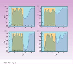
The traditional solution to this problem using transport theory gives transmissivity equals to 1. We have evaluated this problem using the method described in the sidebar, however, with one term in the sum (because we consider transmission perpendicular to the parallel layers, that is, a quasi-one-dimensional problem) for 5 and 10 layers (potential barriers) for two cases:
1. layers are periodic with thickness 1 (relative units), spacing 1, and potentials equal to 1 (dimensionless units)
2. layers have thickness randomly uniformly distributed between 0.5 and 1.5, and potentials of the layers are randomly uniformly distributed between 0.5 and 1.
The results of our evaluation are expressed in terms of transmissivity versus reciprocal wavelength (see
Fig. 2). For the periodic layers, the system tends to have a transparent band (|t|2 = 1) when the number of layers increases. In the case of random layers, the system does not have the same continuous band with a unit transmissivity. Increasing the number of layers does not create such a continuous transparent band with transmissivity equal to 1, but it can create an isolated narrow transparent window (localized state).
Restoring images in an optical tomograph
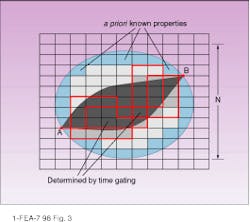
The ability to restore the image and spatial resolution of the optical tomograph can be improved by adding prior information about the medium (which is especially significant for continuous-wave measurements) or by time-gating. If the linear size of the domain is N cells, then its surface area is proportional to N2. The experimental setup and interpolation technique make it possible to get a set of measured values on each surface cell (see Fig. 3). In this case there are only N2 equations to restore N3 volume cells. If we know a priori information about the part of the domain with the volume K3 cells (for example, the area near the surface), the relation between these numbers should be N2 > N3 - K3 to restore all cells (note that the problem is nonlinear).
It should be noted that exact information about a part of the object (even a small part) is better than approximate assignment of optical coefficients to the whole MRI map of the biological object. The error margin of the assigned parameters can overlap with the deviation of these parameters in tumors and other anomalies. This circumstance can lead to artifacts and degradation of accuracy.
The best result can be achieved with a time-gated signal, however. In the case of the time-gating, we can estimate time resolution for separate spatial trajectories. If the average velocity of light in the medium is
Dt = tm- tn ª L(jm - jn)/
Also defining the number of steps jmax is equivalent to reducing the number of variables in the inverse problem. Further, time gating provides us with the equivalent of separation of variables in the inverse problem. Independent measurement of yin and yout on the given time interval Dt is equivalent to the separation of variables for
Eq. 7 (in sidebar) because it allows getting reflection and transmission simultaneously at points A and B (see Fig. 3).
Overall, this process allow us to estimate requirements for the experimental setup and inverse solver. And trajectories found from the equations weighted with the calculated probabilities give the profile of light distribution in the medium. In fact, the process can be treated phenomenologically (for example, in combination with the method described by S. B. Colak14) for evaluation or adjustment of the deblurring function (evaluation between two points on the surface, as in Fig. 3) or of the point-spread function (between the point on the surface and surface area on the opposite side). Ultimately this approach should allow for more-rapid and effective solutions to the inverse problem for optical tomographic imaging. o
REFERENCES
1. B. Chance et al., "Photon migration in muscle and bone," in Photon Migration in Tissues, B. Chance, ed. (Plenum Press, NY, 1988).
2. R. Nossal et al., Appl. Optics 27, 3382 (1988).
3. R. Aronson et al., "Application of transport theory to infrared medical imaging," in Modern Mathematical Methods in Transport Theory, in series Operator Theory: Advances and Applications (Birkhauser Press, 1989).
4. V. V. Varadan and V. K. Varadan, eds., Multiple Scattering of Waves in Random Media and Random Surfaces (Penn State Univ. Press,
University Park, 1985).
5. A. Ishimarn, Wave Propagation and Scattering in Random Media, Vols. 1 and 2 (Academic Press, NY, 1978)
6. R. Berkovits and S. Feng, Phys. Reports 238,135 (1994).
7. Th. M. Nieuwenhuizen and J. M. Luck, Phys. Rev. E 48, 569 (1993).
8. I. Khalfin, R. Berkovits, and M. Gitterman, Phys. Rev. E 49, 4708 (1994).
9. C. Depeursinge, F. Bevilacqua, and P. Marquet, OSA TOPS on Adv. in Opt. Imaging and Photon Migr., R. Alfano and J. G. Fujimoto, eds., 2 (OSA, 1996).
10. Y. Yamamato and R. E. Slusher, Phys. Today, 66 (June 1993).
11. V. Freilikher, M. Pustilnik, I. Yurkevich, Phys. Rev. B 50, 6017 (1994).
12. A. Figotin and I. Khalfin, "Bound states of a one-band model for 3D periodic medium," preprint Dept. of Mathematics, UNCC (Nov.1996); J. Comput. Phys. 138, 153 (1997).
13. D. W. L. Sprung, Hua Wu, and J. Martorell, Am. J. Phys. 61, 1118 (1993).
14. S. B. Colak et al., Appl. Opt. 36,180 (1997).
FIGURE 1. An actual optical tomograph would require more source-detector pairs than shown here to provide adequate spatial resolution.
Mathematics of optical tomography
To calculate transmissivity and intensity maps, we consider a periodic medium (discretized) containing defects (biological objects) that occupy an arbitrary number of cells. It can be shown that the complete solution for the discrete three-dimensional Schrödinger-like equation is equivalent to the one-band approximation for this equation on the lattice:12
(1a)
where l and y are eigenvalue and eigenfunction, respectively, and TS is the Schrödinger operator;
(1b)
where x is a point in three-dimensional space, and t(x) describes the periodic medium with a defect and can be expressed as t(x) = t0(x) + d t(x). Here t0(x) represents the periodic function describing the underlying medium and where the perturbation d t(x), referred to as defects, is assumed to vanish outside a bounded domain L (that is, considered an object). The described approach has no restrictions on the magnitude of d t(x). Then, the spatial inhomogeneities are considered as a system of such defects on the lattice.12
To go from a description of the medium to a solution for the light-scattering problem that can be used in tomographic imaging, we use Green`s function formalism to calculate the transmission of light (transmission from point A to point B is a measured value determined by optical properties of the whole domain, as each cell of the domain participates in the light transmission).
We note that eigenfunctions of Eq. 1 associated with the eigenvalue l are exponentially bound. Then Green`s function with the eigenvalue l for Eq. 1 on the lattice between the points x and y inside domain L can be expressed as
(2a)
where
(2b)
Here j counts coordinates in the three-dimensional space and k belongs to the reciprocal lattice. Taking into account that x-y can have only integral values, Green`s function can be expressed as12
(3)
where r1, r2, and r3 denote spatial coordinates measured in the numbers of cells in the discretized domain and Rj is.
(4)
Such a representation of Green`s function can be considered as a probability of travel between two points separated by the distance x(r1, r2, r3) on the lattice over all paths within the object, and Rj, corresponds to all routes with j steps. Equations 3 and 4 completely describe Green`s function and represent in fact decomposition of Green`s function to the set of probable trajectories. This makes it possible to restore eigenfunctions of Eq. 1 that define the transmissivity map.
At this point, it is interesting to apply our decomposition for the analysis of the uniqueness of the solution to the inverse imaging problem and improvement of spatial resolution. Because the path along each trajectory can be treated as a one-dimensional problem, we can consider the transfer matrix that describes propagation of a wave through a set of one-dimensional barriers.13 The solution for the Schrödinger equation for the single barrier in this case can be decomposed into the two waves: "in" and "out":
(5)
The transfer matrix M can be expressed as
(6)
where the transmission coefficient, t, and reflection coefficient, r, are determined by the potential and the size of the barrier, and matrix M is Hermitian. The set yin,outL,R is the set of measured values. Because |t|2 and |r|2 have been found for each cell, the inverse problem is solved. The scattering problem in these terms, using Eq. 4 can be expressed as
(7)
where sum counts all possible trajectories from r1+r2+r3 steps till jmax steps, and Njmax is the normalization equal to the number of all counted trajectories. It has been chosen from the requirement that the transfer matrix for the transparent system is equal to 1. Here we guess that we know a priori the effective number jmax of the steps in the longest probable trajectory.
I. K.
FIGURE 2. Transmissivity of the system is shown with five barriers (a and b) and with 10 barriers (c and d) vs. reciprocal wavelength (relative units) The cases of periodic barriers with constant potential are on (a) and (c). Randomly placed barriers with random potentials are on (b) and (d). Boxes show the band with transmissivity equal to 1 when the number of periodic barriers with constant potential goes to infinity.
FIGURE 3. Green`s function between points A and B can be expressed as a probability of reaching point B from point A on the lattice along all possible routes. Methods for improving spatial resolution include using prior knowledge of optical properties near the surface layer (light blue) to decrease the volume to be restored, and using a time-gated signal to restrict the length of the path, the number of trajectories, and, in turn, the number of cells to be restored (dark gray) for a given source-detector pair.


