OPTICAL TEST EQUIPMENT: Ensquared and encircled energy testing attains 'automated' status
KENT WEED AND TONY HOLLOWAY
Optical engineers commonly rely on data gathered from single-wavelength interferometer or polychromatic modulation transfer function (MTF) tests to quantify optical system performance and ensure compliance with customer design specifications. However, the often overlooked ensquared or encircled energy test method can provide even greater accuracy, application flexibility, and cost efficiencies. Ensquared/encircled energy (EE) testing is particularly useful in evaluating the performance of optical systems that form an image of a point source where the fraction of energy in a small square or circle compared with the total energy in the spot is of interest.
Advantages of EE Testing
In its simplest form, EE testing is the measurement of the amount of light inside a small (often pixel-sized) aperture compared to the light inside the entire focused spot at the focal plane of an optical system. Practically speaking, the higher the EE value, the tighter and more concentrated is the light within the spot.
The use of EE testing offers optical engineers the capability of testing a system’s flexibility over broad spectral ranges, without the large investment usually required for specific-wavelength interferometers. Although this testing method is not new, it has generally been too costly, complicated, and inflexible for common use. But recent hardware and software innovations using computer-controlled automation means engineers can now use EE measurements to determine a multitude of performance parameters of a lens assembly, including through-focus EE and depth of focus, field curvature, field tilt, boresight, field of view (FOV), distortion, effective focal length (EFL), flange focal length (FFL), relative illumination, and general spot size and quality—all with just one automated test (see “Optical performance parameters that can be obtained through EE test data”).
The test setup
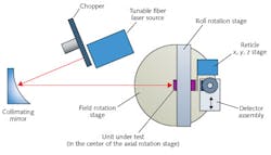
The EE test setup includes an appropriate wavelength source that is either collimated or placed at a finite conjugate distance (see Fig. 1). Assuming that the test will be run over the entire FOV of the lens assembly under test, either the source or the lens needs to be dynamically positioned relative to the other. This is generally done more easily by moving the lens under test using two tip-tilt type mounts, or by using two rotary mounts. Motorized stages under automated computer control can easily accomplish the multiple measurements that are typically required.
There is a lot of flexibility with EE testing in choosing the illumination source. The EE method is often used for multispectral testing where chromatic aberrations are of interest, although narrowband testing is possible as well. Typical sources include white light, passband-filtered light, and use of narrowband filters, laser lines, and monochromators. Of course, the amount of energy needs to be sufficient for the receiving detector to deliver a high signal-to-noise ratio (SNR). Using a chopper and lock-in amplifier in the test setup can significantly improve SNR.
In a typical EE test layout, the design of the interface mount between the lens and the axial rotation stage has several important considerations. If multiple lenses are to be tested and the boresight of the lens is important, then this interface should consider kinematic and beam-alignment features. Likewise, axial positioning calibration should be considered if FFL measurements are required.
The reticle
The heart of any EE test setup is the focal-plane reticle used to pass or reject incoming rays from the system under test. The reticle typically consists of patterns of round or square apertures that dictate whether encircled or ensquared energy tests will be performed, respectively. The shape of the opening creates the difference in these two test types wherein a round aperture results in “encircled energy” data and a square aperture produces “ensquared energy” results. Because many systems generally utilize focal planes with square pixels, ensquared energy (using a square reticle aperture) is the most common choice.
The required reticle may be fabricated in two primary ways: using a metal film on a glass substrate (such as chrome-on-glass) or using a flat metal element with air-hole apertures. For metal-on-glass apertures, the metal film must be sufficiently opaque to thoroughly block any unwanted signal and resulting stray light. A good antireflective coating on the glass within the apertures is desirable to optimize the test throughput. Flat metal substrates with air apertures can avoid metal-on-glass pitfalls; however, current metal-on-glass fabrication technologies can produce significantly more accurate apertures than air holes in metal substrates.
The reticle should have two (or more) working apertures in order to produce the EE measurement ratio—a series of smaller apertures often called the “pixel apertures” and a single larger aperture called the “world aperture.” The world aperture is typically 10 times larger than the pixel aperture and located at least 10 times the distance from the pixel aperture locations. It is fairly inexpensive to design and purchase custom pixel/world reticles; in fact, other shapes on the reticle are now available to help facilitate different types of tests. For example, a larger opening with a straight edge can be used for knife-edge scans, a slit aperture can be used for spot “slit scans,” or an aperture much smaller than the focused spot can be used to map the spot intensity distribution.
As mentioned earlier, if the lens FFL measurement is desired, then the position of the reticle’s surface will need to be calibrated during the final integration of the test equipment setup to ensure that the reticle is at the proper distance and moves perpendicularly to the lens axis within the test equipment’s tolerance allowance.
Positioning the receiver
The detector’s sensitivity to the wavelength for the test is critical. Another important consideration is the detector’s area uniformity. The detector should be positioned such that the same area is utilized for all field positions, assuming that the angle of acceptance is not exceeded. The spot size on the detector can also be quite large to help average out these effects, since the actual focus will be at the reticle and the detector is used in the mode of a light bucket.
The reticle and the detector can move together across the focus when testing a telecentric lens, but the detector will have to move independent of the reticle when testing other types of lenses. If a double rotation stage is used in the mode of the first stage defining the field angle, and the second stage defining the rotational position of the lens under test, the independent motion required for the detector can be limited to a single linear motion.
Programming the control software is an often time-consuming task but can save engineers many hours during EE testing, depending on the number of points to be tested per lens and the number of lenses to be tested. Important matters to consider before programming are calibration requirements, reticle-positioning methods, spot-center location methods, and processes for finding the best focus position for the article under test. Programming must also consider the data output format that may be needed beyond the typical pass-fail criteria. Other outputs such as field tilt, field curvature, and relative illumination may help diagnose lens performance problems.
Collecting actual test data
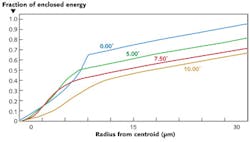
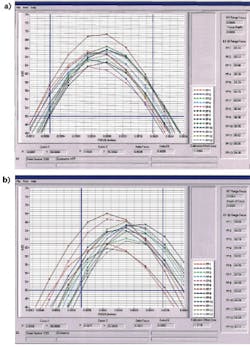
The process for collecting test data is simple in concept but often complex in the details (see Fig. 2). The on-axis position is typically the first data point collected. Here, the world aperture in the test reticle is positioned in the assumed center of the field. Assuming the test setup is properly aligned, the detector behind the reticle should receive the full signal, typically measured in total watts. The world aperture is then scanned left/right and up/down to assure the full signal is being detected. By monitoring power drop-off, the near-exact center of the spot is determined and recorded. Next, the pixel aperture—round for encircled energy, square for ensquared energy—is positioned at the predetermined spot center. This reticle should also be scanned up/down, left/right to ensure the peak energy is being sensed (the hottest part of the spot).Typical cost drivers
When considering EE testing, the most common cost drivers include the number of test field points, the number of through-focus measurements, the required stage accuracy, the size/complexity of the lens mount, whether FFL and/or boresight data is needed, the light source, type of detector, expected SNR, and the possibility of stray light affecting the results. It is also a very good idea to consider creating and retaining a “golden unit” to ensure that the test equipment is stable and repeatable, especially if many tests over a long period are expected.
Uncovering an overlooked test option
When designing complex optical systems for customer applications, more often than not, customers do not realize that EE testing is even available to them. LightWorks Optics recently recommended to NASA, the Department of Defense, and several commercial customers that EE testing be conducted in the product-verification phase of their optical programs, in lieu of the traditional test methods recommended in typical optical system specifications. All of these customers were more than surprised to see the tangible cost and performance benefits that resulted from switching their requirements definitions from traditional wavefront or MTF testing to EE testing. The flexibility and broad data-gathering capabilities of automated, computer-controlled EE testing now makes this often-overlooked test method a viable option, providing engineers the tools they need to improve accuracy and cost effectiveness while delivering verified optical performance.
| Optical performance parameters that can be obtained through EE test data | |
| Parameter | Method |
| Through-focus EE and depth of focus | By measuring EE at several different through-focus positions, the depth of the lens focus can be calculated. |
| Field curvature | Since the position of each field point is known and the best focus axial location of each field point is known, the field curvature can be determined. |
| Field tilt | Field tilt can be determined using the same data as field curvature but with a different evaluation of the average best plane and its angle relative to the desired optical axis. |
| Boresight | Assuming that the lens mount angle is known, the boresight angle of the lens assembly can be determined. Another method used to find boresight is measuring the position of the on-axis focused spot and using the motorized stage to rotate the lens by 180° to measure the spot position a second time. The boresight error will be half the distance traveled by the spot. Boresight shifts in the realm of 50 µrad can often be resolved when using this technique. |
| Center of the focused spot | By using the edge of the “world” aperture, the edge of a larger purposefully designed aperture, or an alternatively designed slit aperture, the center of the energy of a spot can be determined by scanning through the spot in orthogonal directions. |
| Distortion | Since the center of the spot can be determined and the field angles are known (dependent on the reticle stage and lens field rotary-stage accuracy and repeatability), the lateral distortion of the lens can be calculated. |
| Effective focal length (EFL) | EFL can be determined by using the field angle of the lens relative to the source (field rotary stage) and the image height determined by the reticle’s position in the lens focal plane. |
| Flange focal length (FFL) | By calibrating the lens mount to reticle distance, the FFL can be determined to a high degree of accuracy, including field curvature and tilts. |
| Relative illumination | Signal strength data from the EE testing can be used to evaluate the relative illumination of the lens under test. |
| General spot size and quality | By using the same techniques described above for center of the focused spot, some additional information about the general aberrations in the spot such as coma can be deciphered. |
| Stray light | Using the “world” aperture to scan outside of the intended field position, stray light can be detected and evaluated. |
Kent Weed is vice president of engineering and Tony Holloway is supervisor, manufacturing and test, for LightWorks Optics, 14192 Chambers Rd., Tustin, CA 92780; e-mail: [email protected]; www.lightworksoptics.com.


