A hot and dusty Indy car racetrack is not exactly the place you would expect to find free-space optics (FSO) making a name for itself. But the optical-wireless company fSONA Communications (Vancouver, BC, Canada) has teamed with the Indy Racing League (IRL) to better bridge the "last-mile" data-communications gap on racetracks all over the United States using fSONA's optical wireless system.
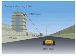
Rather than the radio frequency–based wireless systems traditionally used to transmit critical telemetry race data from the scoring tower to the pit cart, the IRL is now using an optical Fast Ethernet link operating at 100 Mbit/s (see figure). According to Jon Koskey, director of timing and scoring for the IRL, the optical approach allows each team to see critical timing, scoring, and lap information in near-real-time during pre-race qualification, practice sessions, and on race day. The entire system is mounted on metal poles and tripods for stability and transportability; the system is being moved from racetrack to racetrack for each IRL event (16 races in all, including one in Japan).
For each Indy Racing League installation, a wireless optical transmitter is mounted on the scoring tower and the receiver is mounted on the pit cart. The data is distributed to each racing team in near-real time over an optical 100-Mbit/s Fast Ethernet link.
"The necessity to move to a reliable, high-speed wireless connectivity was driven by some new applications to be used in the pits that we had developed for our racing teams," Koskey said. "The previous solution—a 2.4-Gbit frequency-hopping system with a maximum bandwidth of 3 MHz—did not have the bandwidth and was not as reliable because of the saturation of 2.4-Gbit wireless for other networking devices and equipment used by television production companies."
Optical wireless communication typically uses an 850- or 1550-nm laser beam to achieve a line-of-sight link. A standard installation comprises an optical transceiver with a laser transmitter, a receiver, and pointing and tracking systems. After being emitted by the laser, the optical pulses are focused by a lens and sent out as a collimated beam of light that disperses with distance. When the photons reach the aperture lens of the receiver, they are focused onto a photodetector that converts the pulses into an electrical signal. The receiver then amplifies and regenerates the electronic signal, completing the data-transfer link.
For years, the FSO industry has had to battle the perception that environmental factors such as moisture and weather can wreak havoc on an optical wireless connection. A racetrack offers several additional challenges because of heat, exhaust, and dirt generated by the cars. The fSONA multilaser design, however, overcomes these issues, according to Pablo Bandera, technical manager at fSONA. Various system configurations have redundant 1550-nm laser diodes transmitting at distances of 50 to 4600 m. The IRL system, which is optimized for short distances, uses two laser transmitters (compared to the company's higher-end systems, which contain four lasers) emitting 100 mW of power (two transmitters at 50 mW each). The receiver is basically a telescope, with a 10-cm primary mirror that collects the incoming light and focuses it onto a single photodetector.
According to Bandera, the lasers transmit the exact same data in parallel. Each beam has a divergence of 2 mrad so that at some point the beams overlap. This two-beam design gives the system an inherent redundancy by ensuring that the optimum number of photons hit the receiver. The fSONA design also compensates for scintillation—the hot air from the track and engines that rises in waves and can cause a single beam to shift around.
