Ophthalmology: Optical-integration instrument measures intraocular stray light
In the human eye, ocular stray light is the veiling glare that strikes the retina far away from the intended focal spot on the eye’s retina—up to ~5° away, in fact. It is traditionally measured by tests such as having a person look at a bright point object, then asking what the person sees; such indirect measurements provide little or no quantitative information. Previous attempts to design instruments to measure ocular stray light have resulted in devices that only measure out to about 0.5°, missing much of the problematic glare.
Researchers at the Laboratorio de Optica, Universidad de Murcia (Spain), and the Institute of Vision and Optics, University of Crete, Heraklion, Greece have come up with a simple ophthalmic instrument based on double-pass optical integration, which measures ocular stray light at angles between 3° and 8° and is suitable for use in a clinical setting.1
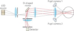
The instrument's light source is an array of LEDs emitting at about 530 nm in the green (the region of the spectrum most relevant to vision), with the output homogenized by diffusers (see figure). An off-center optical system projects the source onto the retina, collects the from the stray-light region on the retina, and images this region onto a silicon photomultiplier made by Excelitas (Waltham, MA). A movable slit in front of the detector enables the stray-light region to be scanned.
The LED source is divided into two concentric zones, each of which is modulated at a different rate to allow the signals to be captured separately. The first zone is a 3° diameter disk, modulated at 769 Hz; the second is the surrounding annulus, covering angles between 3° and 8°, modulated at 483 Hz (both frequencies are thus far below the sampling rate of the 48 kHz data-acquisition interface used). A slit-like diaphragm in the illumination arm limits the optical power delivered to the eye to 90 μW at the corneal plane.
Easy alignment to the eye
The instrument has to be positioned to within 1 mm axially and much less than that laterally relative to the eye to be measured. To do this, the researchers added two cameras, one on each side of the instrument’s lens nearest the eye. Both cameras image the eye’s pupil; taking a half-image from each camera and combining them produces a split video output in which the two half-pupils seen on the screen align with each other only at the proper instrument position.
Because two signals are returned during stray-light measurements (the disk and the annulus), the measurement signal is easily normalized. Because the stray-light region actually measured is not infinitesimally small, a numerically calculated lookup table was generated (based on 2D convolutions of point-spread functions with varying amounts of stray light) to correct for the finite region size all across the measurement area.
Measurement in human eyes with varying amounts of stray light induced by a series of diffusing filters that introduce progressively more stray light showed agreement with theory. While the obvious potential clinical application of the instrument is the early diagnosis of cataracts, the researchers also think it will be useful in studies of corneal healing and aqueous- and vitreous-humor transparencies.
REFERENCE
1. H. Ginis et al., Biomed. Opt. Express (2014); doi:10.1364/BOE.5.003036.

John Wallace | Senior Technical Editor (1998-2022)
John Wallace was with Laser Focus World for nearly 25 years, retiring in late June 2022. He obtained a bachelor's degree in mechanical engineering and physics at Rutgers University and a master's in optical engineering at the University of Rochester. Before becoming an editor, John worked as an engineer at RCA, Exxon, Eastman Kodak, and GCA Corporation.
