There are many types of charge-coupled-device (CCD) based cameras available to the engineer and product designer. Black and white or color, single line scan or two-dimensional scan, and a range of resolutions, data-acquisition speeds, sensitivities, and costs are all specifications that come into play during the design and selection period. Digital CCD cameras are generally not used by themselves (in contrast to the ways film-based analog cameras are used); system concerns including illumination sources, lenses and other optical components, video and screen-capture boards, and packaging must also be addressed.
This article surveys some of the various types of CCD cameras and their applications. It also touches briefly on other system components as their selection impacts the camera choices. The table of vendors that follows on p. 144 is a partial listing of camera and array manufacturers. For a more complete listing, see the 1997 Laser Focus World Buyers Guide, p. 372.
Overview of camera types
First, it is necessary to define a few terms. A CCD is a semiconductor imaging device that transports a photoelectrically generated charge packet (information) in a pixel array to a signal amplifier. That is, the CCD array changes the information contained in a stream of light to a digital signal. The strength of the signal is directly and linearly proportional to the intensity of the light.
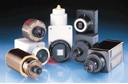
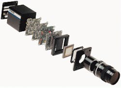
This device can be an array sold as a component or it can be assembled within a camera (see Fig 1). In a digital camera, the array is packaged in a housing with lenses, photodiodes, circuitry for processing the output from the CCD shift registers, and circuits for receiving and processing external clock and shutter signals (see Fig. 2). Finally, you can also obtain a camera system that would include the camera head, a controller, a computer interface board, cabling, and software. There are other types of arrays that are used for camera systems (see Laser Focus World, April 1997, p. 73); this article looks only at CCD-based systems.Imaging arrays for solid-state cameras are available as linear scans (one-dimensional) or as two-dimensional (area or matrix) arrays. In a linear scanning device the imaging area is arranged as a linear array of pixels. A linear array may have as few as 256 elements; 2048-element lengths are common, and longer ones are available. Linear arrays are used for applications such as high-speed document reading, mail sorting, precision optical measurement and gauging, and manufacturing process control.
Matrix arrays (most frequently square, although rectangular configurations are also possible) are commonly available in 256 × 256 and 512 × 512 packages, with high-end versions capable of more than six million pixels of resolution. Camera systems designed around matrix arrays are used in various applications including medical and biomedical imaging, motion control, industrial process control, spectroscopic instrumentation, and noncontact measurement. Special systems have been designed specifically for applications in microscopy and astronomy.
A second criterion for a system designer is whether the camera sees images in black and white or in color. Black-and-white systems can offer higher resolution and faster data-acquisition speeds than color systems. Color can offer the engineer more capability for inspection and visual discrimination and can be especially important in medical and biomedical applications as well as in some industrial process-control applications. Color can be achieved with three cameras, one each for the red, green, and blue wavelengths. Some manufacturers are now furnishing CCD-based cameras that process all of the colors with one array. This solution, however, comes at a price—both of complexity and the actual system cost.
Cameras, like other optical devices, have a spectral region of optimized system performance. Cameras are available that display sensitivity in either the near-infrared, visible, ultraviolet, or x-ray spectral ranges. There are even systems that can simultaneously compare images acquired at up to four different visible wavelengths.
Performance issues
The CCD cameras of the types discussed here are generally used in scientific research or other high-precision work. These applications require high sensitivity and high resolution so that as much of the available information as possible is captured by the camera.
Many of the qualities and features that improve sensitivity and resolution are not typically available in less-expensive devices. For example, variable scan rates and variable exposure times are important in low-light situations, so that more signal (information) can be received by the device. Fill factors, that is, the amount of the signal capture by the pixels, can be 100% (if required), whereas in less costly cameras it may be as low as 25%. Low noise circuitry and cooled CCD operation combine to minimize noise (already low compared to other types of arrays), which improves sensitivity. Finally, a range of pixel sizes is available that allows a designer to optimize the array design for a particular application.
One of the measures of sensitivity of a CCD camera is the quantum efficiency (QE) of the array. The QE measures the percentage of photons reaching the CCD that are converted to electronic signals. Several commonly offered features can compromise the QE of the device. One of these features, anti blooming, decreases the QE by preventing the excessive charge build-up from spilling over onto the adjacent pixels. Performance trade-offs, such as this, abound throughout the selection of a solid-state camera, initially at the device level but, ultimately, in the camera design as well.
Another important measure of device performance is the rate or speed of data acquisition and processing. The standard readout mode is to digitize each pixel of the CCD. Some manufacturers offer an option of slow scanning to minimize further electronic noise. If the device is a high-resolution array with millions of pixels and a low pixel scan rate is being used, then it can take a long time to scan a device. Binning, or combining the charges from groups of pixels, can increase the readout process time. Rows or columns of pixels also can be skipped, so that alignment and sample orientation can be performed quickly, while the full scan is retained only for sample processing.
System components and accessories
After the designer selects the basic array and the camera, choices among the various accessories including lenses, shutters, mounts, controlling software, and the interface with the computer should continue to enhance the performance of the system. Even small additions, such as using antireflection coatings for all of the window surfaces, contribute to improving overall sensitivity.
There can be as many as a half-dozen different factors to take into account when selecting lenses. The array format, field of view, and desired magnification of the object all impact the selection of a suitable lens. The lens-mount system and any lens-protection elements must also be considered.
Both mechanical and electronic shuttering are available; each affects system performance. Mechanical shuttering has speed limitations, while electronic shuttering takes away from the quantum efficiency of the device. Adapters are also available to connect the camera to other instruments, such as telescopes or microscopes, but the buyer must already know the final configuration before purchasing the adapter.
The interface to a computer for image processing and storage is another key criterion in camera selection (see Laser Focus World, April 1996, p. 127). Some camera manufacturers are now offering an integrated selection of serial cards, controllers, cabling, and other electronics so that customers can connect to a PC, a Macintosh, or selected workstations. The controller contains the A/D converters, the timing, the readout controls, and, if necessary, the CCD temperature controls. It is also the power source for the camera system and, as such, can ensure a clean, stable source of power.
Selection of the interface and the computer or workstation can be driven by the speed of image collection and the amount of information that needs to be accessed. Manufacturers offer software packages for both image acquisition and processing, running either under Microsoft Windows on PCs or under a Macintosh-compatible lab program. A library of commands is also available for customers who want to control the camera under their own software programs.
Special applications
There are many special situations for which vendors have optimized a CCD digital camera. Sometimes, enhancement is as simple as offering the correct mount or lens or even modifying software so that the right information can be presented. More complex modifications include designing a system that will operate in a challenging environment, such as in a vacuum, underwater, or on a satellite.
Creating a fiberoptic interface between any flat, light-emitting surface and the CCD is a specialized modification that allows for high throughput and high coupling efficiencies. With 1:1 coupling, fused fiberoptic cameras eliminate the vignetting, distortion, and crosstalk of a typical lens systems. Up to 5:1 image magnification is also possible through a fused-fiber-coupled interface. These cameras are used for imaging flat biological samples, as streak cameras, and as electron microscope scintillators.
One other interesting application is time delay and integration (TDI)—using a rectangular array to gather data in a very-high-speed, low-light situation. Some of the uses of TDI devices include process control of an extrusion machine, imaging products on a conveyor belt, pattern recognition, and noncontact measurement. The charge on the CCD is moved during exposure, precisely coordinated with the movement of the object to be imaged. This arrangement provides much greater sensitivity than a similar setup using a linear array.
This article has only briefly touched on the available alternatives in both arrays and cameras. For work being done in either the UV or the IR, a different set of considerations, as well as vendors, apply. Many other specialty applications are being supported; it is important to discuss your particular setup and intended use of the digital camera with the technical staff of any of the manufacturers.

